凯瑞尔电子材料
1. Introduction
In the realm of Surface Mount Technology (SMT) packaging, the integrity and precision of component packaging directly impact downstream assembly yield and reliability. Among the critical equipment in this process, the CCD (Charge-Coupled Device) inspection taping machine plays a pivotal role in ensuring that components are correctly oriented, defect-free, and securely sealed within carrier tapes. This article delves into the technical aspects of CCD semi-automatic taping machines, exploring their structure, process control, troubleshooting, quality standards, and selection criteria. As a leading provider of SMT packaging solutions, Kairuie Electronic Materials Co., Ltd. offers customizable CCD inspection taping machines designed to meet diverse production needs, from small-batch high-mix to medium-volume high-yield applications.
2. Product Structure & Material Composition
2.1 Machine Architecture
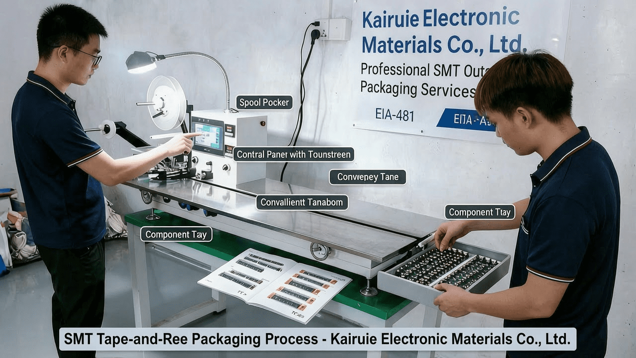
The CCD semi-automatic taping machine integrates several key modules: a manual placement station, a CCD vision inspection unit, an automatic reject removal mechanism, and a sealing & rewinding unit. The machine is compatible with both heat seal and self-adhesive (pressure-sensitive) sealing methods, offering dual-mode switchability for flexibility. It supports carrier tape widths from 8 mm to 56 mm, with customization options up to 88 mm for wider applications.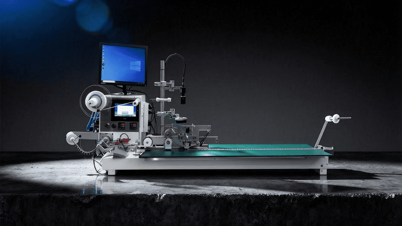
2.2 Vision System Specifications
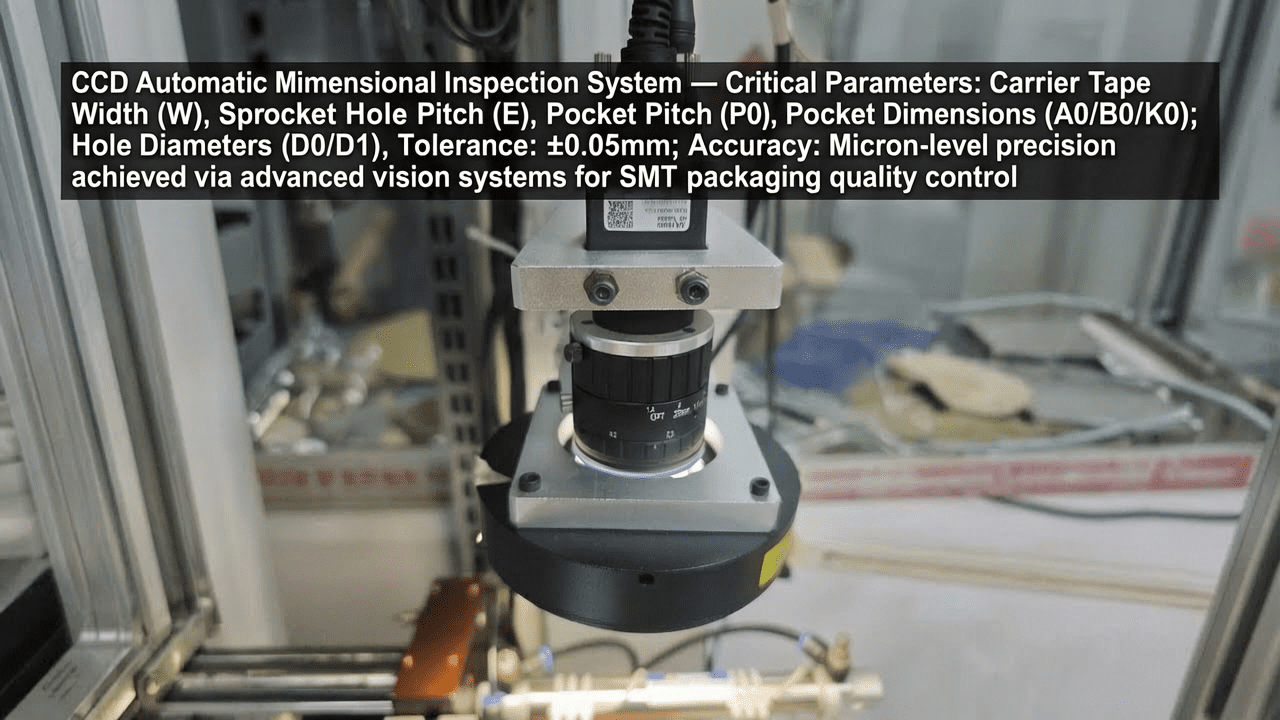
The CCD inspection system employs high-resolution cameras and advanced image processing algorithms to detect component orientation, polarity, marking, and physical defects. Inspection items can be customized based on customer requirements, including but not limited to: component presence/absence, orientation (0° or 180°), polarity marking, and surface defects. The system achieves inspection precision down to ±0.01 mm, ensuring reliable detection of even the smallest components.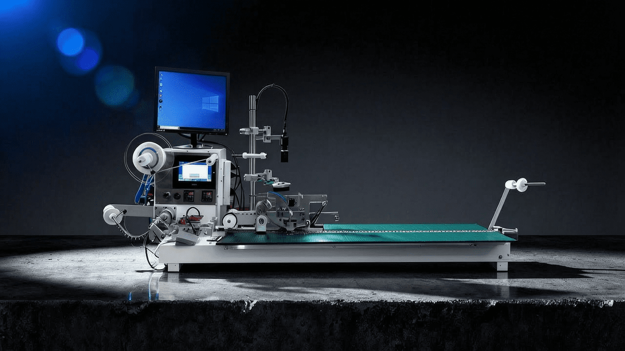
2.3 Sealing Mechanism
The machine supports two sealing modes: heat seal (using a heated die to bond the cover tape to the carrier tape) and self-adhesive (using pressure to apply a pre-coated adhesive cover tape). The sealing temperature range for heat seal is 80°C to 200°C, with a precision of ±2°C. The pressure range is 0.1 to 0.6 MPa, adjustable to suit different tape materials and thicknesses.
3. Core Process Parameter Control
3.1 Temperature, Pressure, and Time
For heat seal mode, the key parameters are sealing temperature, pressure, and dwell time. Recommended ranges: temperature 120°C–180°C, pressure 0.2–0.4 MPa, dwell time 0.5–2.0 seconds. These parameters must be optimized based on the specific cover tape and carrier tape materials. Excessive temperature may cause tape deformation or adhesive oozing, while insufficient temperature leads to weak seals. Pressure too high can crush delicate components, whereas too low results in incomplete bonding.
3.2 Vision Inspection Parameters
CCD inspection parameters include lighting intensity, exposure time, and threshold settings. Proper lighting is critical to highlight component features without glare or shadow. Typical lighting uses red or blue LED arrays with adjustable intensity from 0 to 255. Exposure time is set between 10 µs and 100 µs to capture clear images without motion blur. Threshold values for defect detection are calibrated using golden samples during machine setup.
3.3 Process Window Optimization
To maximize yield and throughput, a Design of Experiments (DOE) approach is recommended to identify the optimal parameter window. For example, a central composite design can map the effects of temperature and pressure on peel strength and sealing appearance. The goal is to achieve a peel strength of 0.2–0.5 N/cm (per EIA-481 standard) while maintaining a seal width tolerance of ±0.2 mm.
4. Common Issues & Troubleshooting
| Symptom | Root Cause | Solution |
|---|---|---|
| Cover tape wrinkles or bubbles | Excessive sealing temperature or pressure; misaligned tape path | Reduce temperature by 10°C; check tape alignment guides; ensure tape tension is uniform |
| Component misalignment in pocket | Incorrect placement position; vibration during indexing | Calibrate placement coordinates; reduce indexing speed; add anti-vibration pads |
| False reject by CCD | Improper lighting; threshold too sensitive; dirty lens | Clean lens; adjust lighting intensity; recalibrate threshold using reference parts |
| Weak seal peel strength | Insufficient temperature or pressure; wrong cover tape type | Increase temperature by 5°C; raise pressure by 0.05 MPa; verify tape compatibility |
| Excessive tape breakage | Sharp edges on guide rollers; excessive tension | Deburr rollers; reduce tension setting; replace worn rollers |
5. Quality Inspection Standards
5.1 Incoming Quality Control (IQC)
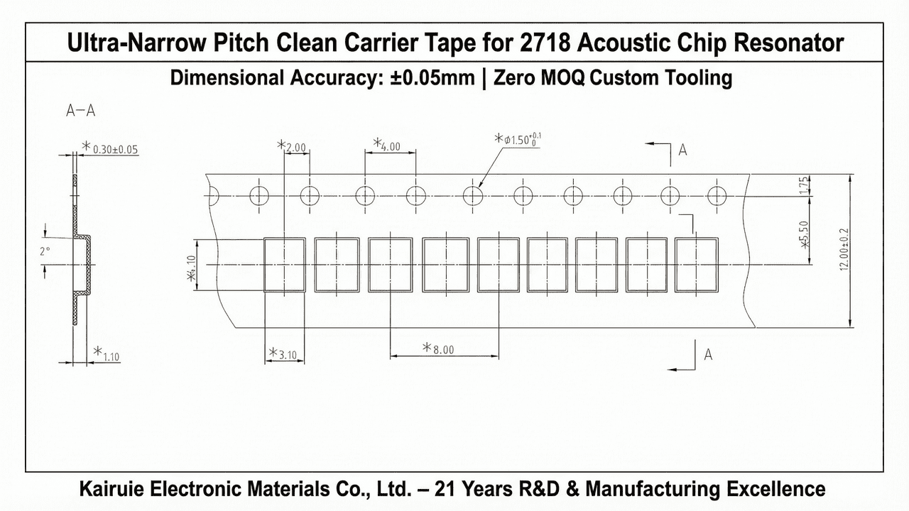
All incoming carrier tapes and cover tapes are inspected for dimensions, visual defects, and peel strength. Carrier tape pocket dimensions are measured using a vision measurement system with ±0.01 mm accuracy. Cover tape adhesion is tested per EIA-481, requiring a peel strength of 0.2–0.5 N/cm at 180° peel angle. Visual inspection under 10× magnification checks for scratches, contamination, and deformation.
5.2 In-Process Quality Control (IPQC)
During production, sampling is performed every 30 minutes or every 1000 components, whichever comes first. Acceptance criteria: no missing components, correct orientation (within ±5°), seal integrity (no open seals), and tape tension within 0.5–2.0 N. Any defect found triggers a 100% inspection of the previous batch and immediate process adjustment.
5.3 Reliability Testing
Reliability tests include: (1) Aging test: packaged tapes stored at 85°C/85%RH for 168 hours, then re-inspected for peel strength and appearance; (2) High/low temperature cycling: -40°C to +85°C for 100 cycles, checking for tape delamination; (3) Transportation simulation: vibration test per ISTA 2A, followed by visual inspection. These tests ensure the packaging withstands real-world conditions.
6. Selection Guide
| Application Scenario | Recommended Machine Model | Key Features |
|---|---|---|
| Small batch, high mix (e.g., prototypes, R&D) | Semi-Automatic Manual Taping Machine | Low cost, quick changeover, manual placement, no CCD |
| Medium volume, high yield (e.g., consumer electronics) | CCD Semi-Automatic Taping Machine | Manual placement + CCD inspection, automatic reject removal, dual sealing modes |
| High volume, automated (e.g., automotive, medical) | Fully Automatic CCD Taping Machine | Vibratory bowl feeding, CCD inspection, automatic marking, high throughput |
For components with strict polarity requirements (e.g., LEDs, diodes), the CCD semi-automatic machine is ideal due to its precise orientation detection. For large components (e.g., connectors), the fully automatic model with custom bowl feeders offers higher efficiency. The semi-automatic manual machine is cost-effective for small batches where human inspection is sufficient.
7. Conclusion
The CCD semi-automatic taping machine represents a balanced solution for SMT packaging, combining manual flexibility with automated vision inspection to ensure component quality and packaging reliability. By integrating precise process control, robust inspection algorithms, and flexible sealing modes, this equipment addresses the needs of modern electronics manufacturing. Kairuie Electronic Materials Co., Ltd. (www.kairuie.com) is dedicated to providing customizable taping solutions that enhance production efficiency and product quality. We invite industry peers to exchange ideas and explore how our technology can support your packaging challenges.