凯瑞尔电子材料
1. Introduction
In the realm of Surface Mount Technology (SMT) packaging, the demand for high-speed, high-precision, and fully automated solutions has never been greater. As electronic components continue to shrink in size and increase in complexity, traditional manual or semi-automatic taping processes struggle to maintain the required throughput and quality consistency. The Fully Automatic CCD Taping Machine with Vibratory Bowl Feeder & Automatic Marking emerges as a game-changing solution, integrating advanced vision inspection, automated marking, and seamless sealing and rewinding into a single, streamlined system. This article delves into the technical intricacies of this cutting-edge equipment, exploring its structure, process parameters, common issues, quality standards, and selection guidelines. By the end, readers will gain a comprehensive understanding of how this technology elevates SMT packaging to new heights of reliability and efficiency.
2. Product Structure & Material Composition
2.1 Layer Structure and Key Components
The Fully Automatic CCD Taping Machine is engineered with a modular architecture that ensures flexibility and precision. The core layers include:
- Base Layer: The machine frame is constructed from high-strength aluminum alloy, providing rigidity and vibration dampening essential for accurate component placement.
- Adhesive Layer: The sealing system supports both Heat Seal and Self-Adhesive modes, switchable based on product requirements. Heat seal uses a thermoplastic adhesive activated by controlled temperature, while self-adhesive employs pressure-sensitive tape.
- Treatment Layer (Optional): For components requiring anti-static protection, an optional ionizer or conductive tape is integrated.
2.2 Key Material Parameters
The machine is compatible with carrier tape widths ranging from 8mm to 56mm (customizable up to 88mm). The vibratory bowl feeder is designed to handle components with dimensions from 0402 to 2520, with a feeding speed of up to 15,000 components per hour. The CCD vision system offers a resolution of 0.01mm, ensuring precise inspection of component orientation, polarity, and defects. The marking unit uses a high-speed inkjet printer with a resolution of 600 dpi, capable of printing alphanumeric codes, date codes, or logos.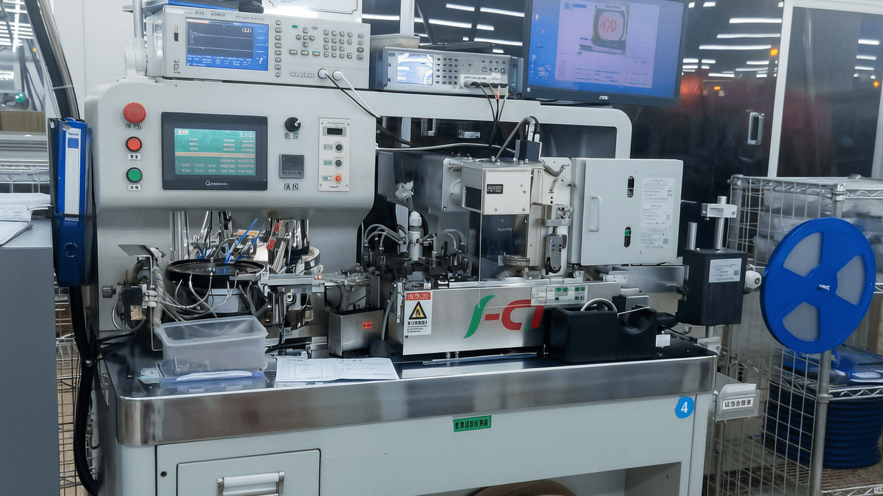
3. Core Process Parameter Control
3.1 Temperature, Pressure, and Time Settings
Optimal process parameters are critical for achieving consistent tape sealing and component integrity. Recommended ranges are as follows:
| Parameter | Heat Seal Mode | Self-Adhesive Mode |
|---|---|---|
| Sealing Temperature | 120–180°C | N/A (room temperature) |
| Sealing Pressure | 0.2–0.6 MPa | 0.1–0.3 MPa |
| Sealing Time | 0.5–2.0 seconds | 0.3–1.0 second |
| Bowl Vibration Frequency | 50–100 Hz | 50–100 Hz |
3.2 Effects on Product Quality
Improper temperature can lead to insufficient adhesion or tape melting. Pressure too high may crush delicate components, while too low causes weak seals. Time settings must balance throughput with bond strength. The vibratory bowl frequency should be tuned to component geometry to prevent jams or misalignment. Process optimization involves iterative adjustment using design of experiments (DOE) to minimize defects.
4. Common Issues & Troubleshooting
| Symptom | Root Cause | Solution |
|---|---|---|
| Components misaligned in pockets | Vibration frequency too high or bowl track worn | Reduce frequency; inspect and replace bowl track |
| Seal peel strength below spec | Temperature too low or pressure insufficient | Increase temperature by 10°C; raise pressure by 0.1 MPa |
| Marking smudged or missing | Inkjet nozzle clogged or timing off | Clean nozzle with solvent; adjust print trigger delay |
| CCD false rejects | Lighting inconsistency or threshold too strict | Calibrate lighting; loosen rejection criteria within spec |
| Excessive tape breakage | Sealing temperature too high or tape tension incorrect | Lower temperature; adjust tensioner spring force |
5. Quality Inspection Standards
5.1 Incoming Quality Control (IQC)
All incoming carrier tapes, cover tapes, and components must pass visual inspection for contamination, dimensional verification using a micrometer, and peel strength testing per EIA-481 standard. Minimum peel strength for heat seal is 0.5 N/cm, and for self-adhesive, 0.3 N/cm.
5.2 In-Process Quality Control (IPQC)
Sampling frequency is set at every 30 minutes or 1,000 components, whichever comes first. Acceptance criteria: defect rate ≤ 0.5%. Visual checks include component alignment, seal integrity, and marking legibility.
5.3 Reliability Testing
Aging tests simulate 72 hours of continuous operation at 40°C and 90% RH. High/low temperature cycling from -40°C to +85°C for 100 cycles validates tape adhesion. Transportation simulation uses random vibration at 5-500 Hz for 2 hours per axis.
6. Selection Guide
| Component Type | Recommended Solution | Key Considerations |
|---|---|---|
| Small passive (0402, 0603) | Vibratory bowl + CCD + auto-marking | High speed, precision alignment |
| Medium ICs (SOP, QFP) | Manual placement + CCD inspection | Flexibility for varied body sizes |
| Large connectors | Semi-automatic manual taping | Cost-effective for low volume |
| High-reliability automotive | Fully automatic with dual inspection | Traceability, zero defect tolerance |
7. Conclusion
The Fully Automatic CCD Taping Machine with Vibratory Bowl Feeder & Automatic Marking represents a pinnacle of SMT packaging automation, delivering unmatched precision, speed, and reliability. By integrating advanced vision inspection, automated marking, and dual-mode sealing, it addresses the most demanding requirements of modern electronics manufacturing. Kairuie Electronic Materials Co., Ltd. is committed to providing innovative solutions that enhance production efficiency and product quality. For more information, visit our website at www.kairuie.com. We warmly invite industry peers to exchange ideas and explore how our technology can transform your packaging processes.


