凯瑞尔电子材料
1. Introduction
USB connectors are ubiquitous in modern electronics, serving as the primary interface for data transfer and power delivery. In Surface Mount Technology (SMT) packaging, carrier tapes play a critical role in protecting and transporting these components during assembly. The design of carrier tapes for USB connectors must address unique challenges such as varying pin counts, shielding requirements, and mechanical stability. This article delves into the technical aspects of USB connector carrier tape design, covering material selection, process parameters, quality control, and troubleshooting. By understanding these specifications, manufacturers can achieve higher yields, reduced downtime, and reliable performance in high-volume production environments.
2. Product Structure & Material Composition
Layer Structure
A typical carrier tape for USB connectors consists of three layers: the base layer (carrier tape), the adhesive layer (cover tape), and optionally a treatment layer for ESD protection. The base layer is usually made of polycarbonate (PC) or polystyrene (PS) due to their excellent dimensional stability and impact resistance. For USB connectors with fine-pitch terminals, a conductive or dissipative material is chosen to prevent electrostatic discharge (ESD) damage. The cover tape is a heat-seal or pressure-sensitive adhesive film that secures the components during shipping and feeding. The adhesive must provide sufficient peel strength without leaving residue on the components.
Key Material Parameters
Key parameters include carrier tape thickness (typically 0.3–0.5 mm for USB connectors), pocket depth (matching component height), and surface resistivity (10^4–10^6 Ω/sq for dissipative materials). The cover tape peel strength should be between 0.1–0.5 N/mm to ensure reliable sealing yet easy opening. For example, Kairuie’s KRT-1000 series carrier tape uses a 0.4 mm thick PC base with a surface resistivity of 10^5 Ω/sq, paired with a heat-seal cover tape having a peel strength of 0.3 N/mm at 180° peel angle.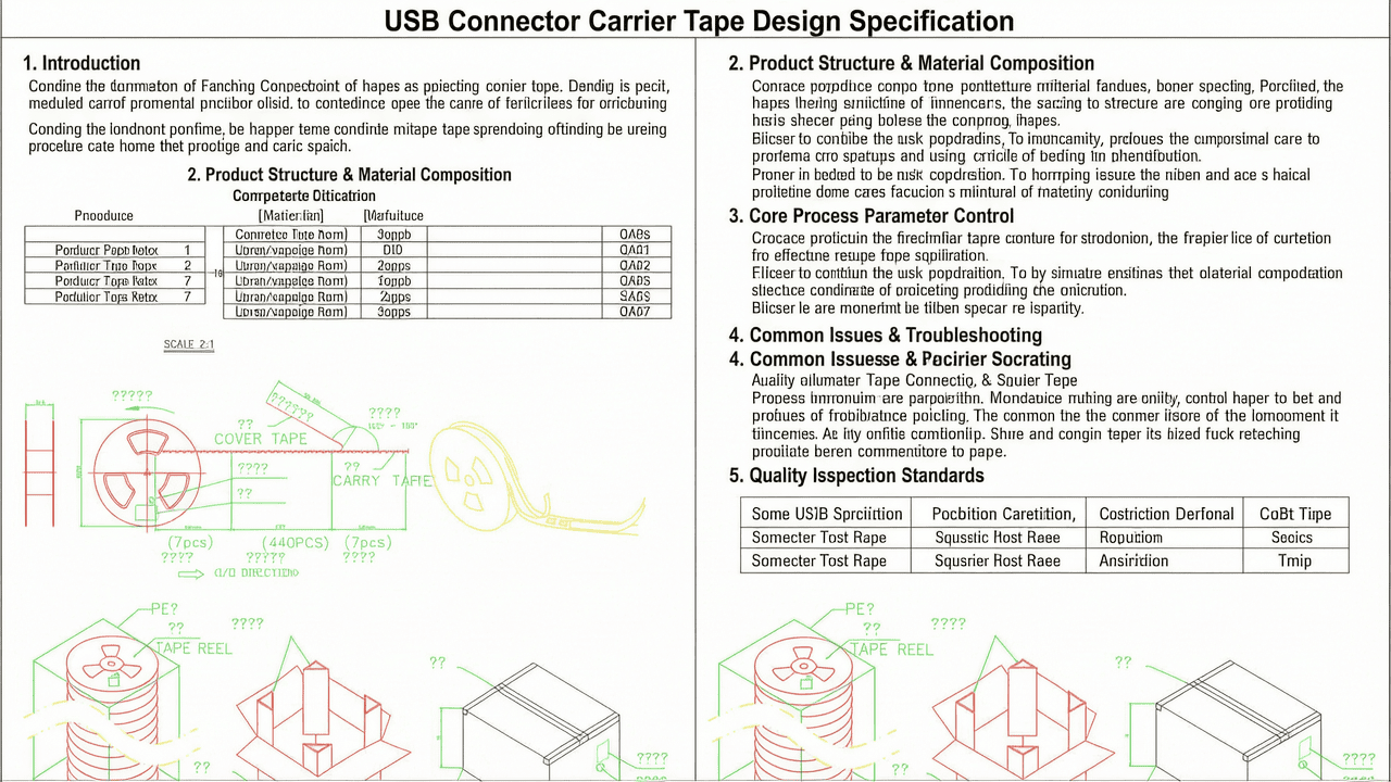
3. Core Process Parameter Control
Temperature, Pressure, and Time
The sealing process for cover tape requires precise control of temperature, pressure, and dwell time. Recommended ranges: sealing temperature 120–160°C (for heat-seal tapes), pressure 0.2–0.5 MPa, and dwell time 0.5–2.0 seconds. For pressure-sensitive tapes, temperature is less critical, but pressure should be 0.3–0.6 MPa with a dwell time of 1–3 seconds. These parameters ensure adequate bond strength without deforming the carrier tape or damaging components.
Effect of Parameters on Quality
Excessive temperature can cause the carrier tape to warp or the cover tape to degrade, leading to poor peel consistency. Insufficient pressure results in weak seals, causing components to dislodge during handling. Optimizing the process window is essential: for a 12 mm wide carrier tape with a 0.4 mm thickness, a sealing temperature of 140°C, pressure of 0.4 MPa, and dwell time of 1.2 seconds typically yields the best results. Adjustments may be needed based on ambient humidity and tape batch variations.
4. Common Issues & Troubleshooting
| Symptom | Root Cause | Solution |
|---|---|---|
| Components pop out during feeding | Low cover tape peel strength; pocket depth too shallow | Increase sealing temperature/pressure; verify pocket depth matches component height |
| Cover tape tears during peeling | Excessive peel strength; cover tape material brittle | Reduce sealing temperature or pressure; switch to lower peel strength tape |
| Carrier tape jams in feeder | Carrier tape warpage; sprocket hole misalignment | Check storage conditions (humidity); verify sprocket hole pitch tolerance (±0.1 mm) |
| ESD damage on connector terminals | Carrier tape surface resistivity too high; inadequate grounding | Use dissipative material (10^6–10^9 Ω/sq); ensure feeder grounding |
5. Quality Inspection Standards
Incoming Quality Control (IQC)
IQC includes visual inspection for scratches, contamination, and dimensional accuracy. Key dimensions: pocket width, depth, pitch, and sprocket hole positions are measured using optical comparators or CMM. Peel strength is tested per IPC-3000 with a 180° peel test at 300 mm/min. Acceptance criteria: peel strength 0.1–0.5 N/mm, pocket depth tolerance ±0.05 mm, pitch tolerance ±0.1 mm.
In-Process Quality Control (IPQC)
During production, sampling frequency is every 1000 pieces or per reel change. Checks include seal integrity (visual), peel strength (destructive sample), and dimensional consistency. Reject if any pocket shows deformation or cover tape lifting. AQL level II (ANSI/ASQ Z1.4) is commonly applied.
Reliability Testing
Reliability tests include aging at 85°C/85% RH for 168 hours, thermal cycling (-40°C to +85°C, 100 cycles), and transportation vibration simulation (ISTA 2A). After testing, peel strength must remain within 80% of initial value, and no component displacement is allowed.
6. Selection Guide
Choosing the right carrier tape depends on USB connector type, volume, and ESD requirements. Below is a comparison for common scenarios.
| Application Scenario | Recommended Product | Key Features |
|---|---|---|
| Standard USB 2.0 Type-A (through-hole) | Paper punched carrier + basic cover tape | Low cost; suitable for low volume; not for ESD-sensitive |
| USB 3.0/3.1 Type-C (SMD, fine pitch) | PC embossed carrier (dissipative) + heat-seal cover tape | Precision pockets; ESD protection; high dimensional stability |
| USB-C with high pin count (24 pins) | PC embossed carrier (conductive) + conductive cover tape | Low surface resistivity (<10^4 Ω/sq); robust sealing for heavy components |
| Automotive-grade USB connectors | PC embossed carrier (high temp) + heat-seal tape with desiccant | Meets AEC-Q200; moisture barrier; high reliability |
7. Conclusion
Proper carrier tape design for USB connectors is essential to ensure reliable SMT assembly. By selecting materials with appropriate ESD properties, controlling sealing parameters within optimal ranges, and adhering to rigorous quality standards, manufacturers can minimize defects and maximize throughput. Kairuie Electronic Materials Co., Ltd. offers a comprehensive range of carrier tapes and cover tapes tailored to USB connector packaging, including conductive and dissipative options with precise dimensional tolerances. For more information, visit our website at www.kairuie.com. We welcome industry peers to exchange ideas and collaborate on advancing packaging solutions for next-generation connectors.


