凯瑞尔电子材料
1. Introduction
Integrated molded inductors are critical passive components in modern surface-mount technology (SMT), widely used in power management, filtering, and DC-DC conversion circuits. Their compact size, high current handling, and magnetic shielding make them indispensable in automotive, consumer electronics, and industrial applications. However, during the high-speed tape-and-reel packaging process—a prerequisite for automated pick-and-place assembly—inductors are susceptible to mechanical damage, particularly edge chipping. This defect can lead to performance degradation, solderability issues, and field failures. As SMT assembly lines push for faster throughput and higher reliability, understanding and mitigating edge chipping becomes paramount. This article explores the root causes of edge chipping in traditional integrated molded inductors during tape-and-reel packaging and proposes systematic solutions through optimized carrier tape design, precise process control, equipment innovation, and rigorous quality inspection. We draw on industry standards such as EIA-481 and insights from Kairuie Electronic Materials Co., Ltd., a leading provider of SMT packaging materials and automation solutions.
2. Product Structure & Material Composition
Effective prevention of edge chipping begins with a thorough understanding of the packaging materials that directly contact the inductor. In tape-and-reel packaging, the carrier tape and cover tape form a protective cavity that must shield the component from mechanical stress, electrostatic discharge (ESD), and environmental contamination. This section dissects the material layers, key parameters, and performance specifications of typical packaging materials, referencing EIA-481 guidelines and Kairuie’s product capabilities.
2.1 Carrier Tape Material and Structure
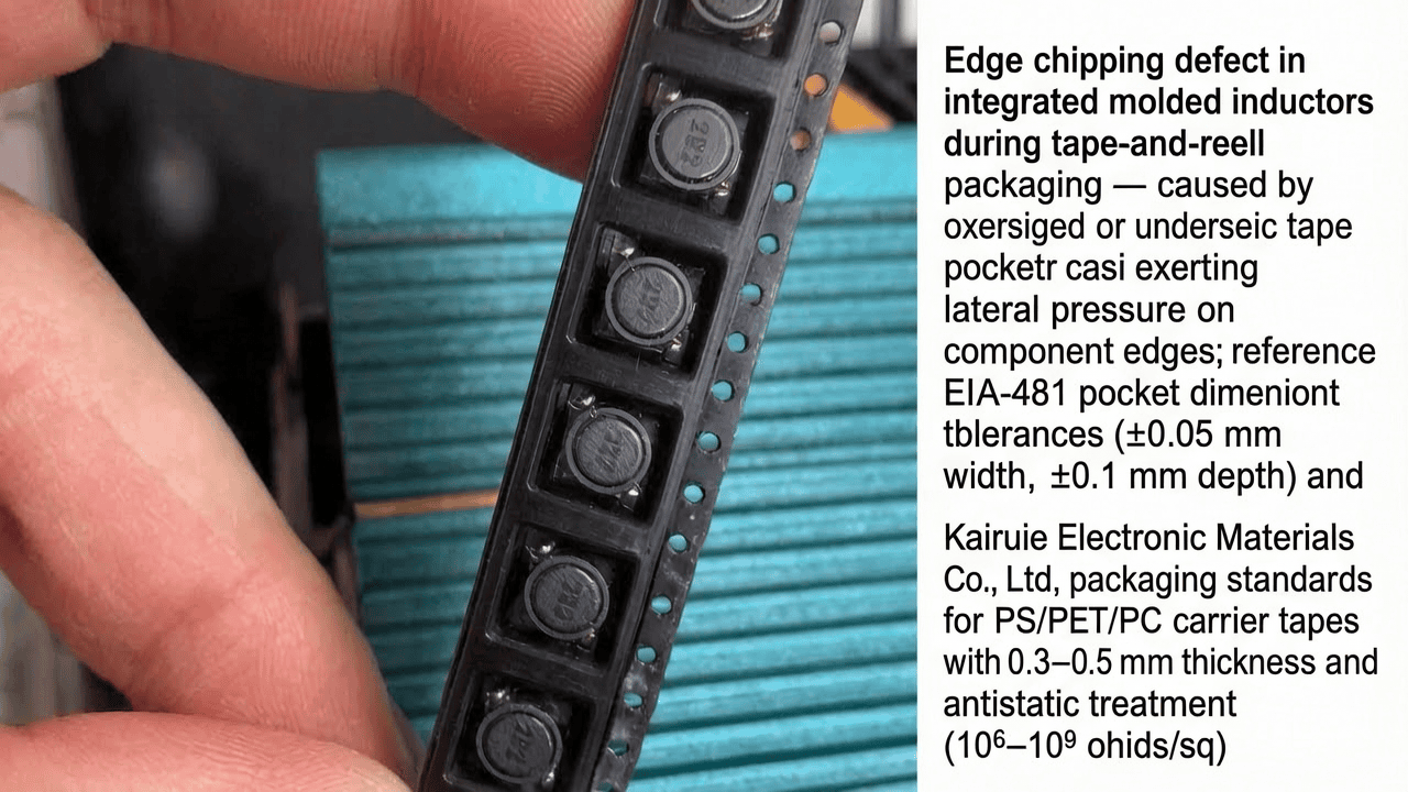
The carrier tape is an embossed plastic strip with precisely formed pockets to hold components. For molded inductors, a rigid material with high dimensional stability is essential. Common substrates include polystyrene (PS), polyethylene terephthalate (PET), and polycarbonate (PC). The pocket depth must accommodate the inductor’s height plus a clearance of 0.1–0.3 mm to prevent contact with the cover tape during sealing. Oversized pockets allow component shifting and tumbling, while undersized pockets exert lateral pressure on the inductor edges, directly causing chipping. According to EIA-481, pocket dimensions are specified with tolerances of ±0.05 mm for width and ±0.1 mm for depth to ensure consistent component orientation. For 8-mm-wide tape typically used for small inductors, pocket width ranges from 1.5 to 7.5 mm. Antistatic treatment is critical; surface resistivity should be between 106 and 109 ohms/sq to prevent ESD damage. Kairuie’s carrier tape line, available in widths from 8 to 56 mm (customizable up to 88 mm), meets these stringent dimensional and ESD standards, employing a PET base layer with a thickness of 0.3–0.5 mm for superior impact resistance and warp control.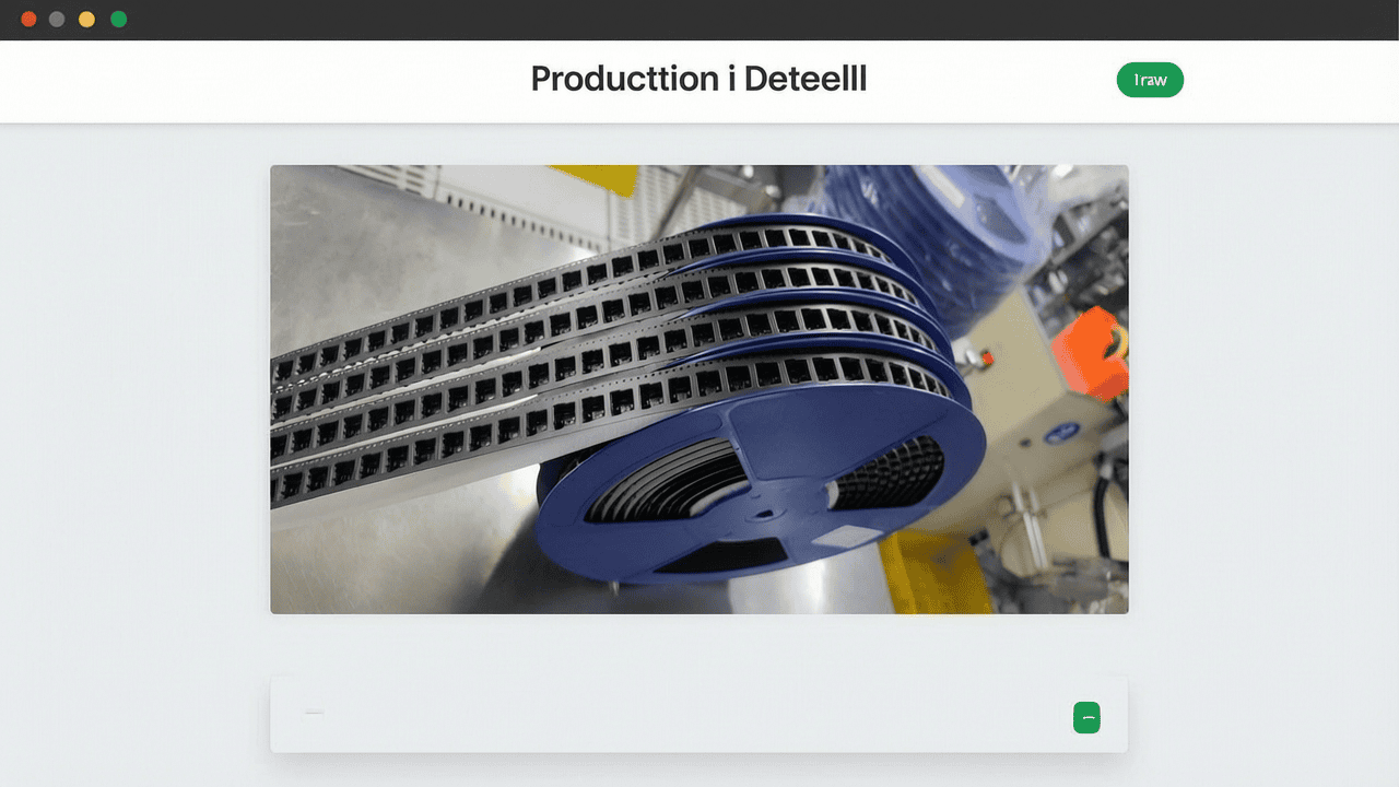
2.2 Cover Tape Configurations
The cover tape seals the carrier tape pocket, and its selection directly influences the stress applied during peeling and sealing. Two main types exist: heat-seal and pressure-sensitive (self-adhesive). Heat-seal cover tapes use a polyolefin or EVA-based adhesive layer activated at temperatures of 120–190°C, providing a strong, uniform bond. Self-adhesive tapes rely on acrylic or silicone adhesives with an initial tack that requires only mechanical pressure. The choice between them affects process parameters and residual stress. For heat-seal tapes, PET film thicknesses of 0.05–0.07 mm and adhesive coat weights of 15–25 g/m² are typical. Cover tape peel strength, measured per EIA-481, should be 0.5–2.5 N for reliable feeding without premature opening. Kairuie’s advanced packaging equipment accommodates both heat-seal and self-adhesive tapes with a dual-mode, switchable sealing system, allowing manufacturers to match tape type to inductor sensitivity.
2.3 Compatibility with Packaging Equipment
The interaction between packaging materials and equipment is critical. Modern machines, like Kairuie’s manual placement + CCD vision inspection + automatic reject removal + automatic sealing & rewinding system, handle carrier tape widths from 8 to 56 mm (customizable to 88 mm) and achieve indexing speeds up to 100 strokes per minute. The CCD inspection module detects edge chips down to 0.05 mm, automatically rejecting defective units before sealing. This closed-loop process ensures that only intact inductors enter the sealed tape, drastically reducing customer returns. The smooth, vibration-controlled indexing mechanism minimizes additional mechanical shock that could exacerbate chipping during packaging.
3. Core Process Parameter Control
Packaging process parameters must be tightly controlled to prevent edge chipping. The primary factors are sealing temperature, pressure, dwell time, and indexing tension. Incorrect settings can subject inductors to thermal or mechanical stress, initiating cracks. This chapter provides recommended ranges and optimization strategies.
3.1 Sealing Parameters: Temperature, Pressure, and Time
For heat-seal cover tape, sealing temperature is typically set between 150 and 190°C, with a dwell time of 0.1–0.3 seconds and roller pressure of 0.2–0.5 MPa. Excessive temperature can soften the PET film and transmit heat to the inductor, potentially damaging magnetic cores. Overpressure directly compresses the component, leading to edge chipping or core cracking. Conversely, insufficient temperature or pressure results in weak bonds and cover tape lifting during reeling. For self-adhesive tape, roller pressure alone is the key; a range of 0.3–0.6 MPa is common. A systematic design of experiments (DOE) should be used to optimize these parameters, with peel strength as a response variable. Kairuie’s equipment features a PID-controlled sealing module that maintains temperature within ±1°C and pressure within ±0.02 MPa, ensuring repeatable bond quality without component damage.
3.2 Indexing Speed and Feeder Tension
High-speed indexing subjects the carrier tape to rapid acceleration and deceleration. If the feeder mechanism has excessive backlash or uneven tension, the tape can jerk or vibrate, causing inductors to rattle within pockets. Tension should be maintained at 0.5–1.5 N for 8-mm tape and proportionally higher for wider tapes. Kairuie’s machine employs a servo-driven indexing system with tension feedback, reducing peak acceleration forces by 30% compared to traditional belt drives. Additionally, the manual placement station allows operators to load components gently, but subsequent reject removal ensures that any damaged parts—whether from handling or machine-induced forces—are removed prior to sealing.
3.3 Process Window Optimization
The ideal process window is established by evaluating the interaction between carrier tape design and process settings. A robust window allows for minor material variations without inducing chipping. For a 2.0×1.6×1.0 mm molded inductor in a 8-mm PET carrier tape, a validated process window might be: temperature 165±5°C, pressure 0.35±0.05 MPa, indexing speed 80±10 spm. Statistical process control (SPC) charts should monitor peel strength and reject rate. Regular maintenance and calibration, as recommended by equipment suppliers like Kairuie, are essential to sustain these narrow tolerances.
4. Common Issues & Troubleshooting
Even with optimal setup, edge chipping and related defects can arise from stray variables. Systematic troubleshooting is vital. The table below summarizes five typical packaging issues, their root causes, and corrective actions.
4.1 Troubleshooting Table for Tape-and-Reel Packaging Defects
| Symptom | Root Cause | Solution |
|---|---|---|
| Edge chipping on inductor corners | Pocket dimensions too small or irregular; excessive sealing pressure | Verify pocket dimensions with optical comparator; adjust pressure to lower end of window; use cushioning layer in pocket if needed |
| Cover tape lifting or premature opening | Insufficient sealing temperature or pressure; contamination on sealing interface | Increase temperature/pressure within spec; clean sealing roller and carrier tape flange; check adhesive shelf life |
| Component upside-down or misrotated | Improper pocket depth or pitch; foreign particles in pocket | Adjust pocket depth to manufacturer recommendation; clean tape prior to loading; use vision inspection to reject misoriented units |
| Tape edge deformation or “spoking” | Excessive reeling tension; misaligned guide rails | Reduce reel torque limiter setting; realign guide rails to ±0.1 mm straightness |
| Intermittent chip-out despite process control | Inconsistent inductor material batch; handling damage before packaging | Implement incoming IQC on inductors; use Kairuie’s CCD reject station to automatically remove chipped parts; review supplier quality |
By addressing these root causes, manufacturers can slash defect rates to below 50 ppm. The integration of automated optical inspection, such as Kairuie’s high-resolution CCD system, adds a crucial safety net, catching defects that escape process control.
5. Quality Inspection Standards
Quality assurance in tape-and-reel packaging spans incoming inspection, in-process monitoring, and reliability validation. Stringent standards are the backbone of customer confidence and low failure rates.
5.1 Incoming Quality Control (IQC)
Before packaging, both carrier tape and inductors undergo IQC. For carrier tape, visual inspection checks for burrs, contamination, and uniform embossing. Dimensional checks—pocket length, width, depth—are performed with a coordinate measuring machine (CMM) or optical comparator, with a sample size per ANSI/ASQ Z1.4 Level II, AQL 0.25. Peel strength of the carrier tape’s antistatic coating is tested per EIA-541. For inductors, 100% visual or automated inspection for edge chips, cracks, and surface defects is recommended, but often a sample-based plan is used; any lot with a defect rate >0.1% is rejected. Proper documentation ensures traceability to material lot.
5.2 In-Process Quality Control (IPQC)
During packaging, IPQC sampling frequency depends on lot size and historical performance. A typical plan is to sample 5 sealed pockets every 30 minutes. The sealed tape is inspected for peel strength (0.5–2.5 N per EIA-481), pocket position, and cover tape alignment. Moreover, Kairuie’s equipment inherently performs 100% CCD inspection of each component before sealing, automatically ejecting units with edge chips larger than 0.05 mm. This real-time sorting not only enhances IPQC effectiveness but also provides data logging for SPC analysis, enabling proactive process adjustment.
5.3 Reliability Testing
To simulate real-world handling, reliability tests include a thermal cycle test (-40°C to +125°C, 100 cycles) to check for cover tape bond degradation or carrier tape warpage, a drop test per ISTA 1A, and transportation simulation with random vibration. After these aged samples are fed through a standard SMT feeder to verify no component hang-ups or peel-stick issues. Successful passing criteria: no cover tape opening, no chipping, and no pocket distortion beyond specification. Kairuie’s packaging materials are pre-qualified for these tests, ensuring robust logistics performance.
6. Selection Guide
Selecting the right combination of carrier tape, cover tape, and packaging equipment is critical for different inductor types and production volumes. The following tables provide guidance based on application requirements.
6.1 Carrier Tape Selection for Molded Inductors
| Component Size (L×W, mm) | Recommended Tape Width (mm) | Pocket Depth (mm) | Material | Key Feature |
|---|---|---|---|---|
| 1.6×0.8 | 8 | 0.6–0.8 | Conductive PS | Low burr, antistatic |
| 2.0×1.2 | 8 | 0.8–1.0 | PET | High rigidity |
| 3.2×2.5 | 12 | 1.2–1.5 | PC | Impact resistant |
| 4.5×4.5 | 16 | 1.5–2.0 | PET | Custom pocket shape |
6.2 Cover Tape and Equipment Configuration
| Application Scenario | Cover Tape Type | Sealing Mode | Recommended Equipment Feature |
|---|---|---|---|
| High-volume, stable environment | Heat-seal | Heat & pressure | Kairuie auto-seal with PID control |
| Low to medium volume, mixed products | Self-adhesive | Pressure only | Kairuie dual-mode, quick changeover |
| Ultra-sensitive inductors | Heat-seal with cushion | Low pressure, extended time | CCD inspection + reject + gentle indexing |
| Wide tape (56–88 mm) for large inductors | Heat-seal | Adjustable pressure profile | Customizable width up to 88 mm |
Kairuie’s tape-and-reel machine, with its CCD vision inspection and automatic reject, is ideal for all scenarios where edge chipping risk must be minimized. Its dual-mode sealing and broad tape width compatibility future-proof the packaging line.
7. Conclusion
Edge chipping in integrated molded inductors during high-speed tape-and-reel packaging is a multifactorial challenge rooted in material, mechanical, and process interactions. By selecting precision-engineered carrier tapes with appropriate pocket dimensions, controlling sealing parameters within a validated window, and deploying advanced equipment with integrated optical inspection, manufacturers can virtually eliminate this defect. Kairuie Electronic Materials Co., Ltd. offers a comprehensive ecosystem of packaging materials and intelligent machinery that directly address these issues. From EIA-481-compliant carrier tapes to our state-of-the-art tape-and-reel packaging system featuring manual placement, CCD vision inspection, automatic reject removal, and dual-mode sealing, we empower the SMT industry to achieve zero-defect packaging. We invite fellow engineers and procurement professionals to visit our website at www.kairuie.com for more technical resources and to explore collaboration opportunities. Together, we can elevate the reliability and efficiency of electronic component packaging.


