
凯瑞尔电子材料
1. Introduction
In the rapidly evolving landscape of Surface Mount Technology (SMT), the ability to adapt to diverse production requirements without sacrificing throughput is the defining characteristic of a competitive manufacturing line. As component miniaturization continues and product life cycles shorten, the bottleneck in SMT assembly has shifted from the placement process itself to the upstream packaging and taping phase. It is here that the concept of operational agility—specifically, the speed at which a line can switch from one component type to another—becomes paramount.
This article provides an in-depth technical analysis of modern SMT packaging solutions, with a specific focus on the transformative power of quick changeover designs. We examine why a reduction in setup time from hours to merely 20–30 minutes is not just a convenience but a critical economic driver. By integrating insights from Kairuie Electronic Materials Co., Ltd.’s latest technological advancements, we will dissect the structural composition of carrier systems, optimize core process parameters, and establish rigorous quality inspection standards. Whether you are managing medium-batch production of automotive electronics or high-volume consumer devices, understanding the synergy between material properties and machinery design is essential for maximizing Overall Equipment Effectiveness (OEE).
2. Product Structure & Material Composition
The foundation of any reliable SMT packaging operation lies in the precise engineering of the carrier tape and its associated reel system. To achieve the stability required for high-speed automated lines—particularly those capable of switching modes within 20–30 minutes—the materials must exhibit exceptional mechanical and electrical properties.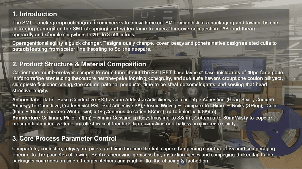
2.1 Layer Architecture and Structural Integrity
Modern carrier tapes, such as those optimized for Kairuie’s packaging systems, typically utilize a multi-layer composite structure designed to balance rigidity with flexibility. The primary base layer is often composed of engineering plastics like Polystyrene (PS) or Polyethylene Terephthalate (PET), selected for their dimensional stability under thermal stress.
Crucially, the interface between the tape and the drive system relies on the flange and hub assembly. According to our technical specifications, Kairuie utilizes an injection-molded one-piece construction for these components. Unlike traditional assembled reels which may develop play or wobble over time, this seamless construction ensures higher tensile strength and concentricity. This structural innovation is vital when discussing quick changeovers; a precisely dimensioned reel allows the packaging machine to calibrate tension and alignment faster, directly contributing to the 20-30 minute setup target.
2.2 Material Parameters and Specifications
The choice of material directly influences the electrostatic discharge (ESD) protection and physical handling of sensitive components. Our product lineup addresses this through specific material grades:
| Parameter Category | Specification / Value | Technical Significance |
|---|---|---|
| Base Material | Conductive PS / Anti-static PET | Ensures mechanical stiffness; prevents static buildup. |
| Cover Tape Adhesion | Heat Seal (HS) / Self-Adhesive (SA) | Dual-mode compatibility allows switching between peeling forces (e.g., 10-50g for SA). |
| Anti-static Grade | Standard / Anti-static | Surface resistivity typically controlled between 10^6 – 10^9 ohms/sq to protect ICs. |
| Color Options | Blue, Black, Transparent, Pink | Transparency aids visual inspection; opaque colors prevent UV degradation or sensor interference. |
| Width Compatibility | 8mm – 56mm (Custom up to 88mm) | Accommodates 0402 chips up to large QFP/BGA packages. |
The dimensional stability highlighted in our knowledge base is particularly critical for the CCD vision inspection systems integrated into semi-automatic and fully automatic machines. If the carrier tape expands or contracts due to humidity changes, the pocket pitch (spacing) shifts, causing the CCD camera to misidentify component positions. By utilizing materials with low moisture absorption rates, we ensure that once the machine is set up, it remains calibrated throughout the run.
3. Core Process Parameter Control
Achieving a 20-30 minute changeover is impossible without robust control over the three pillars of packaging: Temperature, Pressure, and Time. These parameters define the seal quality and component retention force.
3.1 Thermal Management (Temperature)
For Heat Seal (HS) applications, the temperature of the sealing head is the most dynamic variable. Standard operating ranges typically fall between 140°C and 200°C, depending on the cover tape coating.
- Low Range (140-160°C): Suitable for heat-sensitive components or thin PET films. Risk: Weak bond strength leading to accidental opening.
- Standard Range (170-190°C): Optimal for most PS carrier tapes. Provides a peel strength of 10N-30N (approx. 100g-300g), ensuring safety during high-speed pick-and-place operations.
- High Range (>190°C): Used for specialized high-barrier applications. Risk: Melting the carrier tape pocket edges or damaging the component body.
In a quick-change scenario, modern machines utilize pre-heated backup heads or rapid-response ceramic heaters that stabilize within seconds, rather than minutes, allowing operators to dial in the correct temperature immediately after loading a new reel.
3.2 Pressure and Dwell Time Optimization
Pressure, measured in Bar or PSI, must be adjusted according to the width of the carrier tape. An 8mm tape requires less total force than a 56mm tape to achieve the same PSI at the seal interface. Our recommended pressure settings range from 0.2 MPa to 0.6 MPa.
Dwell time (contact duration) works in inverse proportion to temperature. For a 20-30 minute changeover workflow, we recommend using “Recipe Management” software. Instead of manually tweaking knobs, the operator selects a pre-saved profile (e.g., “8mm-0402-Chip-HS”). This instantly sets the pressure regulator and conveyor speed (which dictates dwell time).
3.3 Process Window Suggestions
To maximize the 20-30 minute efficiency window, we suggest the following optimization protocol:
- Pre-staging: Keep tooling (sprockets, guides) for common widths (8mm, 12mm, 16mm, 24mm, 44mm) on a shadow board near the machine.
- Calibration Checks: Utilize the machine’s built-in CCD to run a “Pitch Check” strip immediately after threading. This takes roughly 2 minutes and confirms dimensional accuracy.
- Seal Testing: Perform a destructive peel test on the first 5 sealed pockets. Adjust temperature in ±5°C increments until the fiber-tear (on the cover tape) is consistent.
4. Common Issues & Troubleshooting
Even with the most advanced machinery, variances in raw materials or environmental conditions can lead to defects. Below is a troubleshooting matrix designed to help operators resolve issues without extending the changeover time beyond the 30-minute limit.
| Symptom | Root Cause | Solution |
|---|---|---|
| Jamming / Poor Tracking | 1. Reel hub deformation. 2. Sprocket tooth mismatch. 3. High friction in guides. |
1. Verify flange is injection-molded one-piece (check for cracks). 2. Match sprocket pitch (4mm/2mm) to tape pitch. 3. Clean guide rails; check for burrs. |
| Weak Seal / Cover Tape Lift | 1. Insufficient temperature. 2. Contaminated sealing surface. 3. Low pressure setting. |
1. Increase temp by 10°C increments (max 210°C). 2. Clean the heated anvil with IPA. 3. Regulate pneumatic pressure (target 0.4 MPa). |
| Component Damage (Cracking) | 1. Excessive dwell time/heat. 2. Pocket size mismatch. 3. Rough handling during loading. |
1. Reduce temp or increase conveyor speed. 2. Check pocket CAD drawing vs component dimensions. 3. Review manual placement technique (if semi-auto). |
| Static Discharge (ESD) Failure | 1. Using non-anti-static tape. 2. Low humidity environment. 3. Grounding failure. |
1. Switch to Anti-static grade (Pink/Black) material. 2. Install ionizer fans near the sealing zone. 3> Check machine ground impedance (< 1 Ohm). |
| CCD False Rejects | 1. Lighting reflection (glare). 2. Pocket position offset. 3. Camera calibration drift. |
1. Adjust light source angle; use diffused lighting. 2. Re-align tape edge guide sensors. 3> Run auto-calibration routine using master sample. |
5. Quality Inspection Standards
Maintaining high yield rates requires a multi-stage Quality Assurance (QA) approach. When targeting a 20-30 minute changeover, inspection cannot be a bottleneck; it must be integrated into the process flow.
5.1 Incoming Quality Control (IQC)
Before the material even reaches the machine, IQC protocols ensure compatibility.
- Visual Inspection: Check for voids in the carrier tape, clean edges, and uniform color. Transparent tapes allow for easier pre-inspection of pocket depth.
- Dimensional Accuracy: Measure pitch (usually 4mm or 2mm), pocket width/depth, and tape thickness (typically 0.25mm – 0.4mm). Tolerance should be within ±0.05mm.
- Peel Strength Test: Using a tensile tester (such as an Instron or dedicated seal tester), verify the initial peel force. For standard SMT, 0.1N – 0.7N/mm width is typical.
5.2 In-Process Quality Control (IPQC)
During the production run, sampling frequency depends on the batch size. For continuous operation:
- Sampling Frequency: Every 30 minutes or every 4th reel (whichever is more frequent).
- Acceptance Criteria (AQL): Generally AQL 0.65 for major defects (missing components, wrong polarity) and AQL 1.5 for minor defects (slight scuffing on cover tape).
- Automated Inspection: Leverage the CCD vision system mentioned in our key features. It performs 100% inspection for presence, orientation, and marking legibility, automatically rejecting defective pockets before they are sealed and rewound.
5.3 Reliability Testing
To guarantee performance in harsh environments (Automotive/Medical):
- Aging Test: Store sealed samples at 60°C / 90% RH for 192 hours. After conditioning, test peel strength to ensure the adhesive hasn’t degraded.
- High/Low Temperature Cycling: Cycle between -40°C and +85°C. This tests the coefficient of thermal expansion (CTE) match between the carrier tape and the component to prevent “pop-up” issues.
- Transportation Simulation: Random vibration testing (simulating truck transport) to ensure the seal holds and components do not shift within pockets.
6. Selection Guide
Selecting the right packaging configuration is crucial for balancing CapEx (Capital Expenditure) with OpEx (Operational Expenditure). The goal is to minimize the Total Cost of Ownership (TCO) while meeting throughput targets. Based on the Kairuie Electronic Materials portfolio, we categorize solutions by application scenario.
6.1 Decision Matrix
| Scenario | Recommended Solution | Key Advantages | Changeover Estimate |
|---|---|---|---|
| Proto-type / Small Batch (< 5k pcs) |
Manual Semi-Automatic Machine | – Lowest cost entry. – High flexibility for varying sizes. – Manual placement allows handling of irregular shapes. |
N/A (Operator dependent) |
| Medium Batch / High Mix (5k – 50k pcs) |
CCD Semi-Automatic Machine | – Manual loading + CCD inspection. – Ensures high yield (auto-reject). – Ideal for quality-critical apps (Medical/Auto). |
20 – 30 Minutes |
| Mass Production (> 100k pcs) |
Fully Automatic + Marking | – Vibratory bowl feeding (no labor). – Integrated Laser/Inkjet marking (traceability). – Maximized throughput. |
15 – 20 Minutes (Auto-adjust) |
6.2 Component-Specific Recommendations
- Small Passives (01005, 0201, 0402): Use 8mm or 12mm Conductive Black PS tape. High-speed sealing (Heat Seal recommended) is essential to keep cost per unit low.
- ICs / QFPs / BGAs: Use wider tapes (24mm – 56mm). Consider Anti-static Transparent tape for easy visual verification of lead alignment. Self-adhesive cover tape may be preferred to avoid heat exposure to the package body.
- Connectors / Irregular Shapes: Custom pocket tooling is required. Manual Semi-Auto or CCD Semi-Auto is preferred to ensure delicate parts are not damaged by vibratory feeders.
7. Conclusion
The capability to execute a complete packaging line changeover in 20 to 30 minutes represents a paradigm shift in SMT logistics. It transforms the packaging department from a static storage function into a dynamic, responsive node of the supply chain. By combining precision-engineered materials—such as our seamless injection-molded flanges and anti-static carrier tapes—with intelligent machinery featuring dual-mode sealing and CCD inspection, manufacturers can drastically reduce downtime.
At Kairuie Electronic Materials Co., Ltd., we understand that the future of electronics manufacturing lies in the details. From the surface resistivity of our films to the ergonomic design of our quick-change sprockets, every specification is engineered to support your speed and quality goals. We invite industry peers, engineers, and procurement specialists to explore how our tailored solutions can enhance your production metrics.
For further technical consultation, custom material development, or to request a sample trial of our carrier tapes and packaging equipment, please visit our official website at www.kairuie.com. Let us build the supply chain of the future together.

