凯瑞尔电子材料
1. Introduction
In the realm of Surface Mount Technology (SMT), carrier tape is a fundamental packaging material that ensures the safe transit, precise positioning, and reliable delivery of electronic components to the placement machine. Whether it is a tiny chip resistor or a complex QFN package, the carrier tape acts as a bridge between component manufacturing and PCB assembly. Without a well-designed and consistently manufactured carrier tape, the entire SMT line can face issues like missing parts, misalignment, or even damage to sensitive components. At Kairuie Electronic Materials Co., Ltd., we understand these critical demands. This article delves into the technical intricacies of two primary carrier tape types—embossed carrier tape and punched (paper) carrier tape—both falling under our product ID PROD-CT-001. We will explore their structural composition, core process parameters, common troubleshooting methods, quality inspection standards, and a practical selection guide for various SMT applications.
2. Product Structure & Material Composition
2.1 Embossed Carrier Tape
The embossed carrier tape, as its name suggests, features a continuous plastic tape with formed pockets or cavities. These pockets are created through a thermal or mechanical forming process, resulting in a three-dimensional structure that securely houses components. The base layer of this tape is typically made of polystyrene (PS) or polycarbonate (PC), but at Kairuie, we predominantly use high-performance polyethylene terephthalate (PET) due to its excellent dimensional stability and mechanical strength. The standard PET thickness for our PROD-CT-001 embossed tapes ranges from 0.2 mm to 0.5 mm, with 0.3 mm being the most common for general-purpose components. The adhesive layer is a crucial component, typically composed of a pressure-sensitive adhesive (PSA) applied to the bottom of the pockets or as a top cover film adhesive. For ESD-sensitive devices, the tape is treated with a conductive or static dissipative coating, achieving a surface resistivity of 10^4 to 10^6 ohms per square, thus preventing electrostatic discharge during handling and pickup.
2.2 Punched (Paper) Carrier Tape
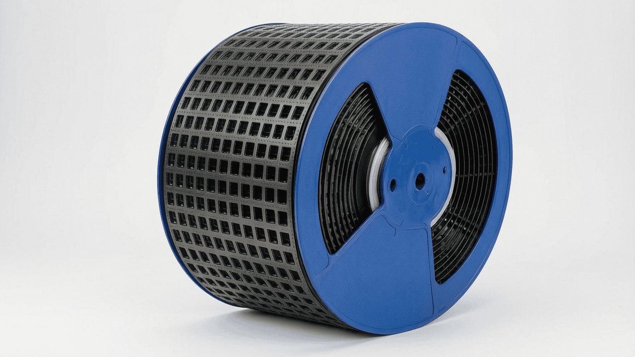
Punched carrier tape, often referred to as paper tape, is constructed from a specially processed paper substrate with punched rectangular holes that serve as pockets. A bottom tape (usually made of polyethylene or a paper-based laminated film) is attached to seal these holes from beneath. The paper thickness is commonly in the range of 0.4 mm to 0.9 mm, accommodating components up to approximately 0.9 mm in thickness. This type of tape is widely adopted for passive components such as chip resistors and capacitors, where cost-effectiveness and high-speed packaging are prioritized. The adhesive layer in paper tape is typically applied as a solvent-based or hot-melt adhesive on the bottom tape, ensuring a strong bond that prevents component loss during winding and unwinding. For ESD protection, our paper tapes are coated with a conductive carbon-based layer, yielding a surface resistivity of less than 10^6 ohms per square. The dimensional accuracy of the punched holes is maintained within ±0.05 mm, ensuring precise pitch alignment for reliable component pickup.
2.3 Key Parameters and Specifications
Under our product ID PROD-CT-001, we offer both tape types with a range of customizable parameters. For embossed tapes, the pocket depth can be adjusted from 0.5 mm to 5.0 mm, and the pitch (distance between pockets) is available in standardized increments such as 4 mm, 8 mm, 12 mm, and 16 mm. The tensile strength of the tape exceeds 50 N/cm, preventing breakage during automated handling. For punched paper tapes, the hole width and height are precisely die-cut, with tolerances of +0.05 mm for width and +0.03 mm for height. The bottom tape’s peel strength is typically in the range of 0.2 to 0.5 N, ensuring easy separation from the top tape without residue. All materials are compliant with RoHS and REACH regulations, and we provide full certificates of conformance.
3. Core Process Parameter Control
3.1 Temperature Settings
Temperature plays a pivotal role in the manufacturing of carrier tapes, especially for embossed tapes. During the forming process, the PET film is heated to a temperature between 120°C and 150°C for a short duration (2 to 5 seconds) to make it pliable enough to form precise pocket shapes. If the temperature is too low, the film may not be fully formed, leading to shallow pockets and insufficient component retention. Conversely, excessive temperature can cause warping, thinning, or even melting of the film, resulting in dimensional inaccuracies. For paper tapes, the adhesive application process requires a temperature of about 80°C to 120°C for hot-melt adhesives to ensure proper flow and bonding. The bottom tape sealing process typically uses a heat-sealing station at around 100°C to 130°C. We recommend maintaining a temperature deviation of ±3°C from the set point to ensure consistent quality.
3.2 Pressure and Time Control
Pressure is another critical parameter, particularly during the lamination of the bottom tape to the paper tape and when sealing the cover tape. For embossed tapes, the pressure used in the forming die must be sufficient to push the film into the mold cavity without causing stress marks. Typical pressures range from 5 to 8 bar for PET films. In the cover tape sealing process, a pressure of 2 to 4 bar is applied for 0.5 to 1 second, ensuring a airtight seal that prevents component shifting but remains easy to peel. For punched paper tapes, the punching process requires a high-speed mechanical press with precise die alignment; the pressure varies depending on the tape width, but a typical value is 2 to 3 tons per square inch. The dwell time for the adhesive curing is equally important—usually 3 to 7 seconds at the specified temperature—to achieve optimal peel strength. Overly long dwell times may cause adhesive bleed, while short times lead to weak bonding.
3.3 Process Window Optimization
Optimizing the process window is essential to maximize yield and minimize defects. For embossed tape forming, we suggest using a Design of Experiments (DoE) approach to determine the ideal temperature-pressure-time combination based on the material batch and component dimensions. A narrower process window should be used for high-precision components, with temperature controlled within ±1°C and pressure within ±0.1 bar. For punching, regular maintenance of the die and a monitoring system that tracks punch wear are critical. A recommended practice is to run a first-article inspection every 1000 meters of tape produced, measuring pocket depth, pitch, and width. By implementing statistical process control (SPC) charts, operators can detect trends and make adjustments before defects occur. At Kairuie, we have refined these parameters to achieve a first-pass yield exceeding 99.5% for our PROD-CT-001 tapes.
4. Common Issues & Troubleshooting
Even with rigorous process control, occasional issues may arise during the production or use of carrier tapes. Below is a table of typical problems encountered in the field, along with their root causes and solutions.
| Symptom | Root Cause | Solution |
|---|---|---|
| Components falling out of pockets during handling or shipping | Insufficient pocket depth or weak cover tape seal | Increase pocket depth by adjusting forming pressure; increase sealing temperature by 5°C or dwell time by 0.2 seconds |
| Cover tape peel strength too high or too low | Incorrect sealing temperature or pressure | Readjust sealing station; recommended peel strength is 0.2-0.5 N for paper tape and 0.3-0.6 N for embossed tape |
| Dimensional discrepancy in pocket pitch | Carrier tape stretching during winding due to high tension | Reduce winding torque and ensure the tape is properly guided; calibrate the indexing sensor |
| ESD discharge causing damage to sensitive components | Surface resistivity exceeds specified range | Apply anti-static coating; measure resistivity periodically and ensure it stays within 10^4-10^6 ohms/sq |
| Punched tape hole deformation at edges | Die wear or excessive punching force | Replace the punching die; reduce press force by 10% and verify hole integrity with a vision system |
5. Quality Inspection Standards
5.1 Incoming Quality Control (IQC)
Every batch of incoming raw materials, such as PET film, paper, and adhesives, is strictly inspected before production. Visual inspection is conducted under 2x magnification to check for scratches, pinholes, discoloration, or contamination. Dimensions are measured using a high-precision micrometer and a coordinate measuring machine (CMM), with tolerances as specified earlier: PET thickness ±0.02 mm, paper thickness ±0.03 mm, and pocket pitch ±0.05 mm. Peel strength is tested using a tensile tester at an angle of 180° with a speed of 300 mm/min. For adhesive-coated materials, we also measure the adhesive coating weight using a solvent extraction method, ensuring it falls within the range of 25-45 g/m² for embossed tapes and 15-30 g/m² for paper tapes. Incoming lots that do not meet these criteria are returned to the supplier, ensuring that only high-quality materials enter our production line.
5.2 In-Process Quality Control (IPQC)
During production, qualified inspectors perform IPQC checks at regular intervals. The sampling frequency is set to every 15 minutes for visual and dimensional inspections, and every hour for peel strength testing. Each sample is taken from the beginning, middle, and end of a roll to ensure homogeneity. Acceptance criteria include: no visible scratches or contamination, pocket dimensions within ±0.05 mm tolerance, pitch deviation no more than 0.1 mm per 1000 mm length, and peel strength within the specified range. In addition, a dynamic test is performed to simulate the actual placement process, where a sample tape is run on a dedicated tester at a speed of 0.5 m/s to check for component displacement or loss. If any defect is found, the entire batch is placed on hold, and corrective actions are implemented. This rigorous approach allows us to maintain a production defect rate of less than 0.1%.
5.3 Reliability Testing
To guarantee long-term performance, our carrier tapes undergo comprehensive reliability testing. An aging test is conducted by storing the tapes at 40°C and 85% relative humidity for 48 hours, after which we verify the dimensional stability (no more than 0.1% shrinkage) and the peel strength retention (at least 90% of the original value). High and low temperature tests expose the tapes to -40°C for 2 hours and then +60°C for 2 hours, cycling for 100 cycles, to ensure that the material does not become brittle or warp. Transportation simulation involves placing the tape reels in a standard shipping box that is subjected to vibration at 10-500 Hz with an acceleration of 2.5 g for 30 minutes in each axis, followed by a drop test from 1 meter onto a concrete surface. After these tests, the tapes are inspected for any deformation, delamination, or degradation of electrical properties. Our PROD-CT-001 tapes withstand all these tests with ease, giving our customers complete confidence in our products.
6. Selection Guide
Selecting the right carrier tape is crucial for optimizing production yield and cost. The decision depends on several factors: component size, weight, shape, and sensitivity to electrostatic discharge. Below is a comparison table that outlines our recommendations for different application scenarios.


