凯瑞尔电子材料
1. Introduction
In modern SMT (Surface Mount Technology) assembly, carrier tapes play a critical role in protecting, transporting, and accurately feeding miniature electronic components into automated pick-and-place systems. For MEMS acoustic resonators, such as the 2718 (2.7×1.8 mm), 3526 (3.5×2.6 mm), and 4030 (4.0×3.0 mm) packages, the demands on carrier tape performance are exceptionally high. These resonators, widely used in silicon microphones, ultrasonic sensors, and high-precision oscillators, are sensitive to electrostatic discharge (ESD), contamination, mechanical shock, and even microscopic particle accumulation. A well-designed cleanroom carrier tape ensures that components arrive at the production line in pristine condition, with zero defects and consistent dimensional orientation.
This article provides a comprehensive technical analysis of cleanroom carrier tapes specifically tailored for the 2718, 3526, and 4030 MEMS acoustic resonators. We delve into product structure, material composition, critical process parameter control, common troubleshooting, quality inspection standards, and a practical selection guide. Throughout, we reference industry standards such as EIA-481 and leverage advanced materials science to help packaging engineers optimize their SMT processes. By understanding the nuances of carrier tape design and application, manufacturers can significantly reduce component loss, improve production yield, and extend the lifespan of their assembled devices.
2. Product Structure & Material Composition
2.1 Multi-Layer Architecture for Precision and Protection
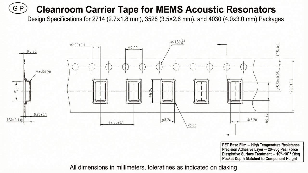
A typical high-performance carrier tape for MEMS resonators comprises three functional layers: a robust base film, a precision adhesive layer, and an optional surface treatment layer for ESD control. The base film provides mechanical integrity and dimensional stability, often made from polyethylene terephthalate (PET), polycarbonate (PC), polystyrene (PS), or polypropylene (PP), depending on the required thermal and mechanical properties. For 2718/3526/4030 resonators, which undergo reflow soldering, PET is the preferred choice due to its high temperature rating of up to 150°C, low shrinkage, and excellent dimensional accuracy. The base film thickness typically ranges from 0.3 to 0.5 mm, with pocket depths meticulously matched to component height (e.g., 1.1 mm for 2718, 1.3 mm for 3526, and 1.5 mm for 4030).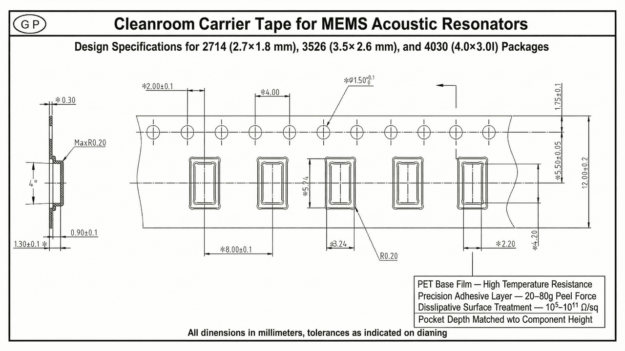
The adhesive layer, usually a heat-activated or pressure-sensitive formulation, bonds the cover tape securely to the carrier tape during packaging. This layer must provide a consistent peel force within the industry-standard range of 20 to 80 grams per EIA-481, ensuring reliable sealing without leaving residues that could contaminate the sensitive resonator surfaces. Kairuie’s advanced carrier tapes incorporate a low-outgassing, cleanroom-compatible adhesive that maintains its properties through temperature cycling and long-term storage.
The surface treatment layer is engineered to control electrostatic discharge. Depending on the antistatic level required, the inner surface of the pocket can exhibit conductive (10³–10⁵ Ω/sq), dissipative (10⁵–10¹¹ Ω/sq), or insulative (>10¹² Ω/sq) characteristics. For most MEMS acoustic resonators, dissipative protection is adequate to prevent static buildup during high-speed unspooling, while for MOSFET-based or ultra-sensitive RF modules, conductive grades may be recommended. Kairuie offers custom antistatic coatings that meet the exacting standards of ISO 14644 cleanroom environments.
2.2 Material Selection and Key Technical Parameters
The selection of carrier tape material directly impacts process yield and component reliability. Table 1 summarizes the common material options, their temperature capabilities, and typical applications in resonator packaging.
| Material | Temperature Rating | Surface Resistivity (Range) | Key Property | Suitable Resonator Size |
|---|---|---|---|---|
| PS (Polystyrene) | 70°C | 10⁵–10¹¹ Ω/sq (dissipative) | Economical, rigid | 4030 (if low-temp process) |
| PP (Polypropylene) | 80°C | 10⁵–10¹¹ Ω/sq | Flexible, chemical-resistant | Not recommended for reflow |
| PC (Polycarbonate) | 120°C | 10³–10¹¹ Ω/sq | High strength, transparent | 3526, 4030 |
| PET (Polyester) | 150°C | 10³–10¹¹ Ω/sq | Dimensionally stable, superior heat resistance | 2718, 3526, 4030 (preferred) |
For the 2718 resonator, with its extremely small footprint, PET’s low thermal expansion coefficient ensures that pockets maintain precise dimensions during reflow profiles peaking at 260°C. The 3526 and 4030 can also benefit from PET, though PC may be a cost-effective alternative when peak temperatures are constrained below 120°C. In addition to the base material, the carrier tape design must comply with EIA-481 pocket geometry: pitch (typically 4 mm for these small components), pocket width/length with adequate clearance (0.15–0.25 mm per side), and proper draft angles to facilitate component pickup. Kairuie’s manufacturing tolerances for pocket dimensions are held to ±0.05 mm, ensuring seamless integration with high-speed placement equipment.
3. Core Process Parameter Control
3.1 Heat Sealing Temperature, Pressure, and Dwell Time
The integrity of the seal between the carrier tape and cover tape is a critical quality determinant. Heat sealing is the most common method, requiring precise control of three parameters: temperature, pressure, and dwell time. For PET-based carrier tapes, the recommended sealing temperature is 150–180°C, for PC it is 130–160°C, and for PS it is 110–130°C. Excessive temperature can cause base film deformation, adhesive ooze, or irreversible antistatic coating degradation, while insufficient temperature leads to weak seals that may open during transport or unwinding.
Sealing pressure should be maintained at 0.3–0.6 MPa, ensuring uniform contact across the seal area without crushing the tape structure. The dwell time, typically 0.5–2.0 seconds, allows the heat to transfer through the cover tape and activate the adhesive. A short dwell time may result in incomplete bonding; an overly long dwell can over-cure the adhesive, reducing its peel strength over time. Process engineers are advised to conduct a design of experiments (DOE) to map the optimal window. For example, a typical starting point for a 3526 PET carrier tape with a heat-activated cover tape is 165°C, 0.4 MPa, and 1.0 second dwell, which yields a peel force of 45–60 grams. Regular calibration and monitoring of sealing equipment are essential to maintain consistency.
3.2 Environmental Control and Cleanliness
Cleanroom conditions are mandatory when packaging MEMS acoustic resonators. A Class 1000 (ISO 6) or better environment minimizes particle contamination that could settle on the resonator diaphragm, causing noise or performance degradation. Humidity should be controlled at 30–60% RH to prevent ESD buildup and protect moisture-sensitive components. Excessive dryness increases static generation, while high humidity can lead to adhesive hydrolysis or condensation. The carrier tape itself should be stored in sealed packaging until use, and operators must wear appropriate ESD garments. Kairuie ensures that its carrier tapes are manufactured in an ISO 14644-certified cleanroom, with online particle monitors and static dissipative production lines, guaranteeing that the tapes arrive free of contaminants and ready for immediate use.
4. Common Issues & Troubleshooting
Even with careful process control, issues can arise in the taping or assembly process. Table 2 outlines the most frequent problems encountered with carrier tapes for miniature resonators, along with their root causes and practical solutions.
| Problem Symptom | Root Cause | Solution |
|---|---|---|
| Inconsistent peel strength across tape width | Uneven sealing pressure or temperature distribution | Verify parallel alignment of sealing bars; calibrate temperature controllers; check for wear on sealing surface |
| Component sticking to cover tape during peel-back | Excessive sealing temperature causing adhesive transfer or component outgassing | Lower sealing temperature by 5–10°C increments; switch to cover tape with lower-tack adhesive; ensure cavity depth adequately clears component height |
| ESD damage detected after packaging | Insufficient antistatic properties or grounding during unspooling | Measure surface resistivity with concentric ring probe; if >10¹¹ Ω/sq, change to conductive grade (<10⁵ Ω/sq) for that batch; verify grounding of all machine parts |
| Pocket dimensional mismatch (component too tight or loose) | Tooling error, material shrinkage, or incorrect specification | Audit tooling dimensions; specify PET for low shrinkage; confirm pocket dimensions against component size plus required clearance (0.15–0.25 mm per side) |
| Tape curl or warpage during storage | Environmental stress or inherent material instability | Store tapes at 23±2°C, 40–60% RH; anneal tape prior to use if necessary; consider thicker base film or alternative material like PET |
By following this guide, operators can quickly diagnose and resolve most issues, minimizing downtime and scrap. Kairuie’s technical support team also provides on-site troubleshooting and rapid analysis of returned samples to identify root causes.
5. Quality Inspection Standards
5.1 Incoming Quality Control (IQC)
Upon receipt of carrier tape reels, a rigorous IQC protocol should be executed. Visual inspection under 10× magnification checks for surface defects, burrs, or contamination in the pockets. Dimensional measurements must verify pocket width, length, depth, and index pitch using a non-contact optical measuring system, with tolerances of ±0.05 mm for pocket dimensions and ±0.1 mm for pitch. Cover tape peel strength is tested per EIA-481: the cover tape is peeled back at a 165–180° angle and 300 mm/min speed, with acceptable values between 20–80 g for tape widths up to 16 mm. Surface resistivity is confirmed with a concentric ring probe, ensuring it falls within the specified range (e.g., 10⁵–10⁷ Ω/sq for dissipative). Additionally, a particle count test may be performed on random samples to ensure compliance with cleanliness requirements.
5.2 In-Process Quality Control (IPQC)
During the taping process, quality checks must be performed at regular intervals—typically once per hour or every 5,000 components packed. The seal integrity is verified by a manual peel test on three consecutive pockets; peel force should remain consistent within ±15% of the nominal value. Machine vision systems inspect for correct component orientation, presence, and pocket occupancy. Any deviation triggers an immediate line stop and adjustment. Statistical process control (SPC) charts track peel force and dimensional data, enabling early detection of process drift. For cleanroom operations, airborne particle counts and ESD workstation compliance are monitored continuously.
5.3 Reliability Testing and Long-Term Stability
To ensure that the carrier tape performs reliably over its shelf life and through the rigors of shipping and storage, a series of reliability tests is recommended. Accelerated aging at 60°C and 90% relative humidity for 72 hours simulates years of controlled storage. Thermal shock testing from -40°C to +125°C (10 cycles) validates that the material does not crack or deform under extreme temperature changes. Vibration testing per ISTA 1A standards replicates transportation stresses. Post-test, the tape is rechecked for peel strength, surface resistivity, and dimensional stability—any degradation beyond ±10% of initial values indicates a potential reliability risk. Kairuie’s carrier tapes are pre-qualified using these tests, with documentation available upon request.
6. Selection Guide
Choosing the right carrier tape configuration for 2718, 3526, and 4030 MEMS acoustic resonators depends on component sensitivity, soldering profile, and handling environment. Table 3 provides a systematic comparison of recommended solutions.


