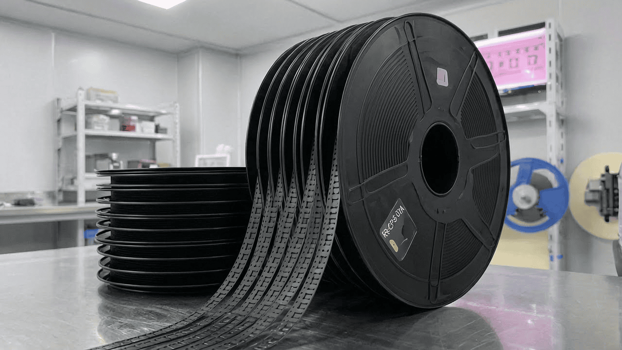
凯瑞尔电子材料
1. Introduction
Surface-mount technology (SMT) has become the backbone of modern electronics manufacturing, enabling high-speed, high-density assembly of components onto printed circuit boards. Among the critical packaging materials that ensure flawless SMT processes, carrier tape plays a pivotal role in protecting, transporting, and presenting surface-mount devices (SMDs) to pick-and-place equipment. Kairuie Electronic Materials Co., Ltd. specializes in precision carrier tapes, and our ±0.05 mm tolerance PS black antistatic carrier tape is specifically engineered for demanding applications such as acoustic chips (MEMS microphones, speakers, receivers). This article delves into the technical intricacies of this product, covering its material composition, critical process parameters, common troubleshooting, quality standards, and selection guidance to help engineers and production managers optimize their SMT lines.
2. Product Structure & Material Composition
2.1 Layer Structure
The Kairuie PS black antistatic carrier tape is a multi-layer composite designed for both mechanical robustness and electrostatic discharge (ESD) protection. The base layer is 0.30 mm thick polystyrene (PS) film, providing dimensional stability and the necessary stiffness for precise pocket formation. The inner surface (component-facing) is coated with a permanent antistatic layer that ensures surface resistivity between 10⁶ and 10⁸ Ω/sq, critical for safeguarding sensitive acoustic MEMS chips from electrostatic damage. Optionally, a topcoat treatment further reduces tribocharging and improves release properties. The adhesive layer for cover tape seal features a heat-activated PSA system compatible with standard sealing equipment, ensuring a reliable peel strength of 40–80 g/10 mm (180° peel, 300 mm/min). Below is a summary of key material parameters for our KR-CPS-08A model frequently used in acoustic chip packaging:
| Parameter | Specification |
|---|---|
| Base Film Material | Polystyrene (PS) |
| Base Thickness | 0.30 ± 0.05 mm |
| Antistatic Coating Type | Permanent, carbon-loaded |
| Surface Resistivity (Inner) | 1×10⁶ – 1×10⁸ Ω/sq |
| Surface Resistivity (Outer) | 1×10¹² – 1×10¹⁴ Ω/sq (insulative) |
| Color | Black (opaque) |
| Pocket Depth Tolerance | ±0.05 mm |
| Cover Tape Adhesion Type | Heat-sealable PSA |
| Peel Strength to Cover Tape | 55 ± 15 g/10 mm |
| Operating Temperature | -40°C to +85°C |
| Particle Count (0.5 µm) | < 100 particles/cm² |
2.2 Dimensional Precision and Tolerance
For acoustic chips, which often contain fragile MEMS structures with dimensions as small as 0.6 mm × 0.3 mm, pocket dimensional accuracy directly impacts pick-and-place yield. Our advanced thermoforming process achieves a pocket depth tolerance of ±0.05 mm and length/width tolerance of ±0.05 mm, exceeding IPC/JEDEC J-STD-033C requirements. This tight control minimizes chip rotation and tombstoning during placement. The carrier tape width is 8 mm, 12 mm, or 16 mm per EIA-481 standards, with sprocket hole pitches of 4 mm for 8 mm width and 8 mm for wider tapes, ensuring smooth advancement in feeders.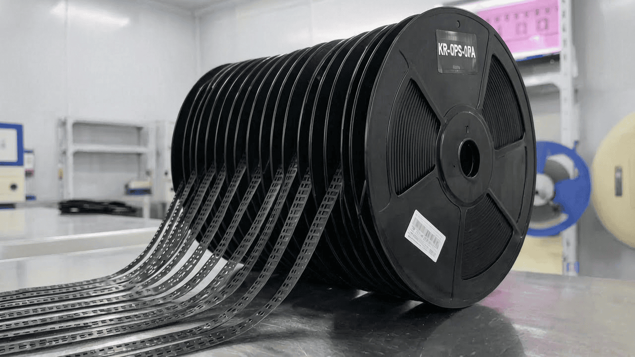
2.3 Cleanroom Manufacturing
Kairuie produces all carrier tapes in an ISO Class 7 (Class 10,000) cleanroom, with online particle monitoring. The black PS material is inherently low-outgassing, and post-thermoforming washing with DI water and ultrasonic cleaning removes residual particles. Final packaging is performed in a Class 5 (Class 100) environment. The result is a product with exceptionally low ionic contamination (Cl- < 1.0 µg/cm², Na+ < 0.5 µg/cm²), essential for preventing corrosion on acoustic chip gold pads.
3. Core Process Parameter Control
3.1 Sealing Temperature and Dwell Time
Cover tape sealing is the most critical step in carrier tape usage. For our KR-CPS-08A with standard heat-seal PSA cover tape (e.g., KR-CT-08H), the recommended sealing temperature range is 160–180°C, with a dwell time of 0.5–1.0 seconds at a pressure of 30–50 psi. If temperature is too low (<150°C), insufficient activation leads to weak adhesion and risk of cover tape lifting during transport. Conversely, temperatures above 190°C can cause the PS base to soften, distort pocket dimensions, or even melt, potentially damaging components. Dwell time should be adjusted proportionally; longer times at lower temperatures can achieve equivalent seal strength but may reduce throughput. Pressure must be uniform across the seal width to prevent peel strength variations.
3.2 Peel Strength Control
Peel strength is a direct function of sealing parameters and cover tape compatibility. Incoming inspection of carrier tape from Kairuie includes a specification of 55 ± 15 g/10 mm when sealed at 170°C, 0.8 s, 40 psi. For SMT lines, it is advisable to perform a daily pull test on sealed tapes using a force gauge. The target is 40–80 g/10 mm for consistent feeder performance. Values below 30 g risk cover tape opening during reel handling; values above 100 g may cause component “stick” to the cover tape, leading to pick-up failures. Process optimization may involve fine-tuning temperature by ±5°C or dwell time by ±0.2 s based on ambient humidity (which can affect PSA tack).
3.3 Storage and Pre-conditioning
Before sealing, both carrier tape and cover tape should be stored in their original packaging at 15–30°C and <60% RH. Pre-conditioning in the production environment for at least 4 hours is recommended to equilibrate moisture content, especially if the tape was stored in a high-humidity warehouse. Excessive moisture in the PS base can cause blistering during heat sealing. Kairuie’s sealed foil bag with desiccant ensures a shelf life of 12 months, but once opened, we recommend consumption within 72 hours or resealing with fresh desiccant.
4. Common Issues & Troubleshooting
| Symptom | Root Cause | Solution |
|---|---|---|
| Cover tape lifts during reel transport | Insufficient sealing temperature/pressure/dwell time | Increase temperature by 5°C or dwell time by 0.2 s; verify pressure uniformity; check cover tape batch compatibility |
| Components stick to cover tape at peel-off | Excessive peel strength; static attraction; cover tape residue | Reduce sealing temperature/dwell; ensure cover tape adhesive is anti-residue; verify surface resistivity of carrier tape inner surface |
| Pocket dimension out of tolerance (undersize) | Excess heat during sealing causing PS shrinkage | Lower sealing temperature; use a bottom support plate to dissipate heat; verify thermoforming precision from supplier |
| High electrostatic discharge (ESD) events at feeder | Degraded antistatic coating; improper grounding | Check surface resistivity with megohmmeter; ensure feeder and tape are grounded; replace tape if resistivity >10^8 Ω/sq |
| Component rotation or misalignment | Excessive pocket clearance; vibration during transport | Specify tighter pocket dimensions; increase cover tape tension or use alternative feeder setting |
4.1 Additional Troubleshooting Insights
For acoustic chips with exposed MEMS diaphragms, even minor particle generation can cause fatal defects. If SEM inspection reveals particles on chips, audit the carrier tape’s cleanroom handling and consider adding an ionized air blow-off station just before sealing. Also, verify that the cover tape does not shed fibers during peel; Kairuie’s KR-CT-08H uses a non-woven conductive top layer to minimize shedding.
5. Quality Inspection Standards
5.1 Incoming Quality Control (IQC)
Upon receipt of Kairuie carrier tape, IQC should inspect: (a) Visual defects: cracks, stains, or blisters under 10× magnification; (b) Dimensional checks: width, sprocket pitch, pocket depth/length/width using optical comparators; all must meet IPC-4811 class 2; (c) Peel strength: seal sample with reference cover tape at standard conditions and measure 180° peel force; (d) Surface resistivity: test both inner and outer surfaces per ANSI/ESD S11.11 using a guarded electrode. A sampling plan of AQL 0.65% per ANSI/ASQ Z1.4 is typical.
5.2 In-Process Quality Control (IPQC)
During SMT production, operators should monitor sealing quality at least once per shift or per reel change. Using a calibrated pull tester, measure peel strength on 5 samples; all must fall within 40–80 g/10 mm. Visual inspection under magnification should confirm no cover tape residue on pocket edges. Additionally, for ESD-sensitive devices, a static field meter can verify that the carrier tape surface voltage does not exceed ±100 V after friction.
5.3 Reliability Testing
Kairuie subjects each production lot to a battery of reliability tests: (a) Thermal aging: 1000 hours at 85°C, after which peel strength and surface resistivity should remain within specification; (b) Temperature cycling: -40°C to +85°C, 500 cycles, no delamination or cracking; (c) Transportation simulation: random vibration per ISTA 1A, 10 hours, followed by functional testing; the tape must maintain integrity and antistatic performance. These tests ensure that acoustic chips remain protected throughout their supply chain journey.
6. Selection Guide
Choosing the right carrier tape depends on chip size, sensitivity, and assembly environment. The table below compares Kairuie’s PS antistatic tape with other common options:
| Application Scenario | Recommended Product | Key Features |
|---|---|---|
| Ultra-small MEMS microphone (0.5 mm × 0.3 mm) | KR-CPS-08A (8 mm width, ±0.03 mm depth tolerance) | Precision pocket; black PS for light-sensitive chips |
| Standard acoustic speaker (2 mm × 2 mm) | KR-CPS-12B (12 mm width, ±0.05 mm tolerance) | Cost-effective, deeper pocket option |
| High-ESD sensitive devices (Class 0) | KR-CPS-08A-ESD (surface resistivity 10⁵–10⁷ Ω/sq) | Conductive version with carbon loading |
| Cleanroom assembly (ISO 5) | KR-CPS-08A-C (ultra-low particle, <50/cm²) | Extra washing and clean packaging |
| High-temperature reflow assembly | KR-PET-08A (PET-based, 120°C peak) | For applications where carrier tape accompanies board through reflow |
For most acoustic chip applications, the KR-CPS-08A series in 8 mm width offers the best balance of precision, ESD safety, and cost. Our engineers can also customize pocket geometries for non-standard packages upon request.
7. Conclusion
Kairuie Electronic Materials Co., Ltd.’s ±0.05 mm tolerance PS black antistatic carrier tape represents a state-of-the-art solution for acoustic chip packaging in SMT. By combining precision thermoforming, controlled antistatic properties, and clean manufacturing, it addresses the critical needs of high-yield, high-reliability assembly. The technical insights provided in this article—from material science to process optimization and quality control—equip engineers with the knowledge to maximize their assembly performance. We invite industry peers to visit www.kairuie.com for detailed technical datasheets, to request samples, or to engage in discussions about future packaging challenges. Together, we can drive innovation in electronic materials.


