凯瑞尔电子材料
1. Introduction
The Critical Role of Reels in SMT Packaging
In surface mount technology (SMT) production lines, the reliable feeding of electronic components is a fundamental prerequisite for high-yield, high-speed assembly. Among the various carrier formats, reels (also called tape-and-reel systems) serve as the backbone for automated pick-and-place operations, especially for chip components, small ICs, LEDs, and an expanding range of semiconductor devices. The 7-inch integrated reel has emerged as a workhorse in the industry due to its balance of capacity, compatibility with standard feeders, and ease of handling. In particular, when dealing with semiconductor chips that are sensitive to electrostatic discharge (ESD) and mechanical shock, the reel must not only provide physical protection but also maintain a controlled electrostatic environment. Kairuie Electronic Materials Co., Ltd. has developed a series of 7-inch integrated reels specifically engineered for these demanding applications, incorporating advanced material science and precision manufacturing to ensure component integrity from packaging to placement.
Objectives of This Technical Article
This article provides a comprehensive technical exploration of the 7-inch integrated reel for semiconductor SMT packaging. We will dissect the product’s structure and material composition, detailing the engineering behind its anti-static properties and dimensional precision. Subsequently, we will discuss core process parameters such as temperature, humidity, and mechanical tension that govern reel performance during winding, storage, and feeder operation. A dedicated section on common issues and troubleshooting will equip production engineers with actionable diagnostics. We will then outline rigorous quality inspection standards, from incoming material checks to reliability testing. Finally, a practical selection guide will help users match reel specifications to specific component types and application scenarios. By the end of this article, readers will have a holistic understanding of how a seemingly simple carrier can significantly impact SMT line efficiency and product reliability.
2. Product Structure & Material Composition
Reel Structure Overview
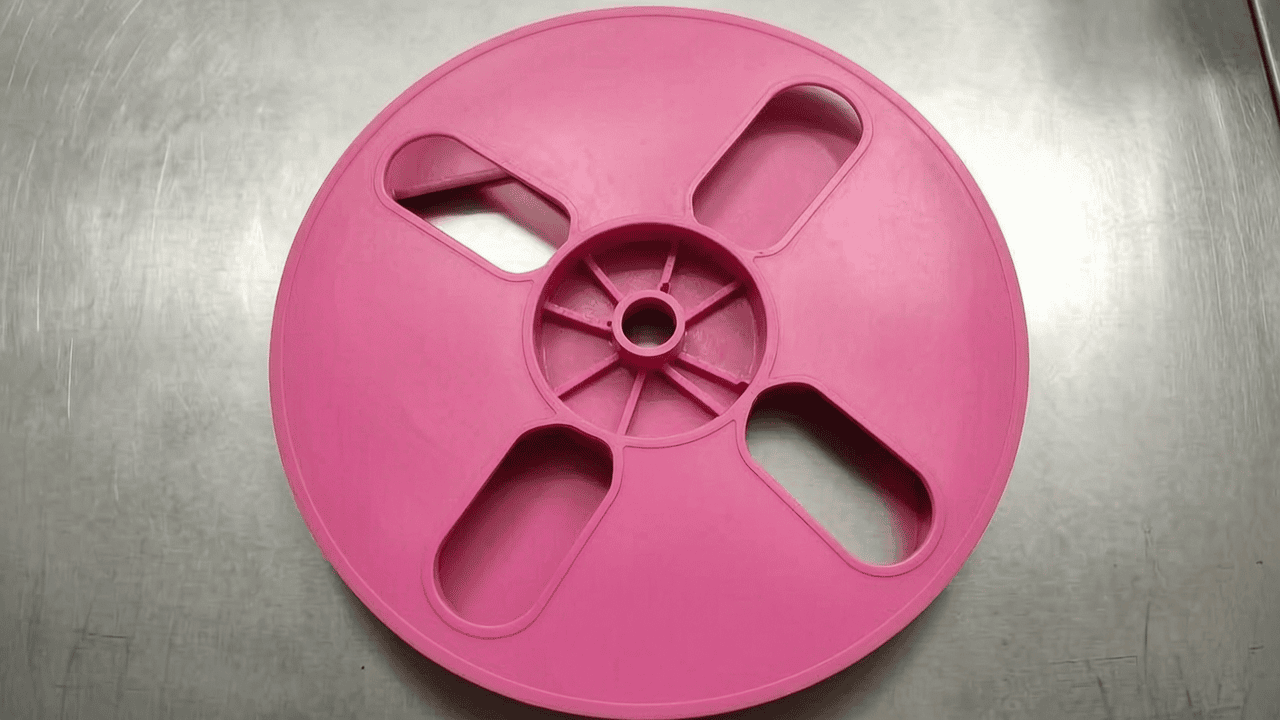
The 7-inch integrated reel from Kairuie is a one-piece molded design that eliminates the assembly weaknesses often found in two-piece or riveted reels. The structure consists of a central hub and two side flanges, all formed from a single material in one injection molding cycle. This monolithic construction ensures perfect concentricity between the hub and flanges, minimizing runout that could cause tape tracking issues during winding or unwinding. The flange surface is engineered with a smooth, burr-free finish to prevent snagging of carrier tape, while the inner hub features keyed or friction-fit geometries (depending on the specific model) for secure engagement with feeder spindles. The reel is available in 7-inch diameter, with hub diameters of 2 inches (approx. 50 mm), 4 inches (approx. 102 mm), 6 inches (approx. 152 mm), and 7 inches (approx. 178 mm), accommodating different tape lengths and winding requirements. The hub diameter directly influences the number of components that can be wound without exceeding the tape’s minimum bend radius, a critical factor for semiconductor devices with delicate lead frames.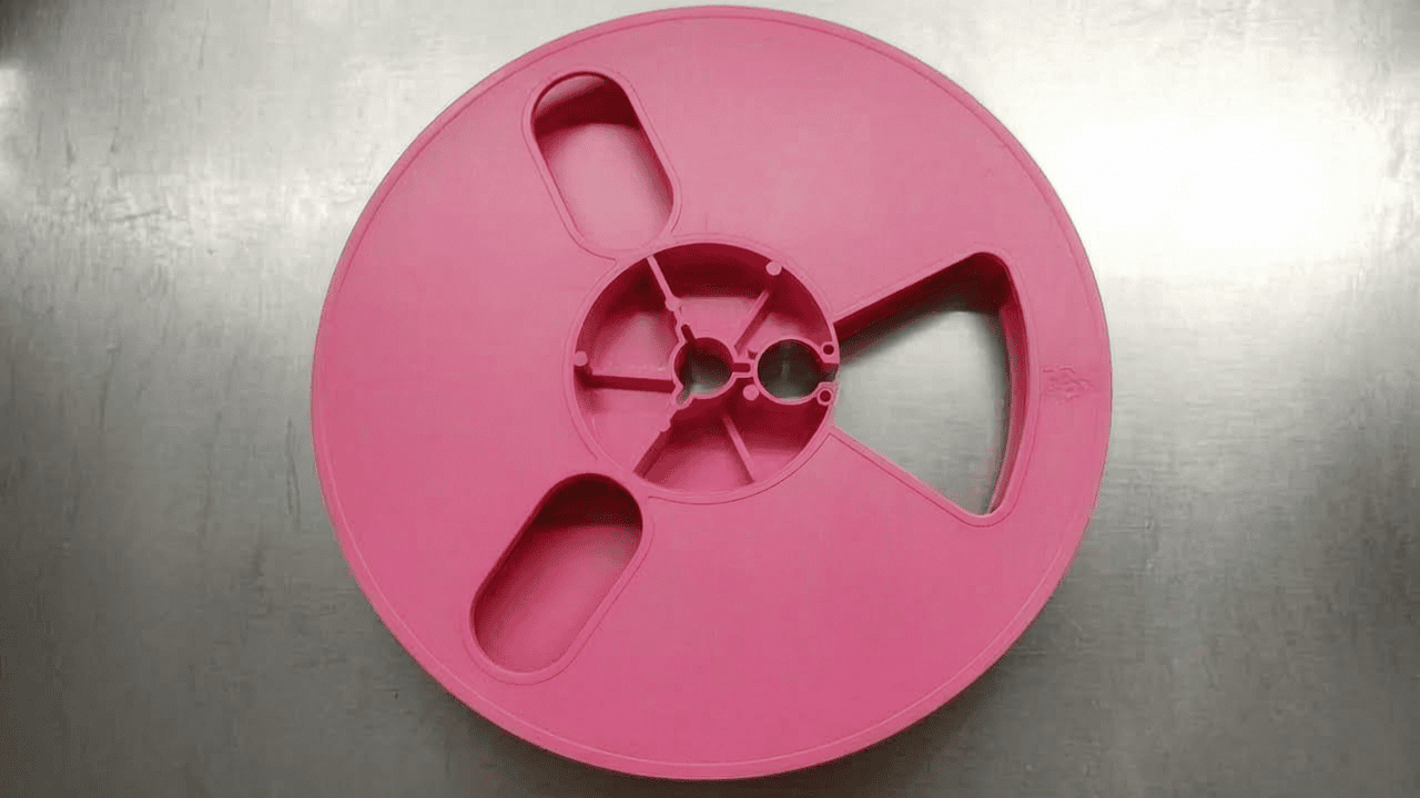
Material Properties and Anti-Static Performance
The base polymer for Kairuie’s 7-inch reels is a high-impact polystyrene (HIPS) or polypropylene (PP), selected for its stiffness, dimensional stability, and compatibility with high-speed molding. For standard applications where ESD protection is not required, the material is used in its natural state, yielding a blue or black color for visual identification. However, semiconductor chips—especially CMOS and GaAs devices—demand stringent static control. For these, the material is compounded with conductive carbon black or migratory anti-static agents to achieve surface resistivities in the dissipative range (106 to 109 Ω/sq) or conductive range (<104 Ω/sq), as per ANSI/ESD S20.20 and IEC 61340-5-1 standards. Kairuie offers anti-static reels in pink (dissipative) and black (conductive) variants. The pink anti-static version uses a non-carbon, non-contaminating additive system that avoids particulate contamination, making it suitable for cleanroom environments. Surface resistivity is measured using a concentric ring probe per ASTM D257, and typical values are consistently controlled between 107 and 108 Ω/sq. The material also exhibits low outgassing (less than 0.1% TML per ASTM E595), ensuring compatibility with vacuum-sealed moisture barrier bags (MBB) used for moisture-sensitive level (MSL) components.
Dimensional Specifications and Hub Design
Precision in reel dimensions is non-negotiable for trouble-free feeder operation. The 7-inch reel’s outer diameter is 178 ± 0.5 mm. Flange width varies from 8 mm to 44 mm, depending on tape width. The hub diameter options—2, 4, 6, and 7 inches—are machined to tolerances of +0.05/–0.00 mm to ensure a snug interference fit on feeder spindles. A critical parameter is hub runout, which Kairuie controls to ≤0.15 mm TIR (Total Indicator Reading). This prevents cyclic variation in tape payout tension. Additionally, the reel is designed to nest stackable profiles for efficient storage and transportation. The table below summarizes typical hub vs. tape capacity relationships:
| Hub Diameter | Typical Tape Length (8mm wide) | Recommended Component Types |
|---|---|---|
| 2 inch (50 mm) | ~500 m | Passive chips, small diodes |
| 4 inch (102 mm) | ~300 m | Small ICs, transistors |
| 6 inch (152 mm) | ~180 m | Larger ICs, connectors |
| 7 inch (178 mm) | ~100 m | Odd-shaped components, heavy packages |
These values ensure the minimum bend radius of the carrier tape is never violated, preserving pocket integrity.
3. Core Process Parameter Control
Temperature and Humidity Control
Proper environmental conditioning of 7-inch reels is essential to maintain their mechanical and electrical performance. Reels should be stored and used within a temperature range of 15°C to 30°C. Exposure to temperatures above 40°C can cause the plastic to soften and warp, leading to flange deformation and hub runout exceeding tolerance. Conversely, temperatures below 0°C make the material brittle, increasing the risk of cracking under impact. Relative humidity should be kept between 30% and 70% RH. High humidity can degrade the surface resistivity of anti-static reels by forming a moisture layer that may leach the migratory additive, reducing its effectiveness over time. For semiconductor applications, it is common practice to bake moisture-sensitive components together with their reels in a dry nitrogen environment at 125°C for several hours—Kairuie’s reels are validated to withstand up to 150°C for short durations without significant dimension change. Process engineers should monitor the storage area’s temperature and humidity with calibrated loggers, and avoid placing reels near heat sources or direct sunlight.
Mechanical Stress and Tension Management
During tape winding, the tensile force applied to the carrier tape must be carefully controlled to prevent elastic stretching or permanent deformation of the tape, which could misalign component pockets. For standard 8mm and 12mm wide tapes, the recommended winding tension is between 50 and 100 grams-force, measured by a digital tension meter at the take-up hub. Excessive tension not only distorts the tape but can also cause the reel flanges to bow inward, compressing the tape layers and damaging components. In the feeder, the back-tension exerted by the reel brake should be adjusted to maintain a smooth payout. Kairuie’s reels are designed with a central boss that provides consistent friction when used with spring-loaded feeders. Operators should verify that the reel’s hub key engages fully with the spindle to avoid slippage. A drop test (1.2 m onto concrete) is part of the reliability validation to ensure the reel does not crack or delaminate under typical handling shocks. In production, routines should include periodic checks of reel flange alignment and spindle lock integrity.
Process Window Optimization
To maximize first-pass yield, users should establish a process window that accounts for reel-related variability. The feeder pick-up position is directly influenced by the reel’s lateral runout; therefore, pick-up teach routines should be performed with the reel loaded and rotated to the maximum runout point. For reels with anti-static coatings, over time, repeated feeding cycles may generate microscopic particulates; a cleaning station with ionized air blow-off at the feeder entrance can mitigate this. Additionally, the reel changeover procedure should minimize downtime: Kairuie’s consistent hub dimensions allow for quick swap without recalibration when using the same model reel. It is recommended to label reels with QR codes containing batch and resistivity data for traceability. By combining these practices with the reel’s inherent precision, a process capability (Cpk) of ≥1.33 for pick-up accuracy is achievable.
4. Common Issues & Troubleshooting
Typical Problems and Solutions
Even with high-quality reels, certain issues may arise due to mishandling, environmental factors, or incorrect setup. The following table catalogues five common problems encountered in SMT production with 7-inch reels, their root causes, and recommended corrective actions. Each entry is distilled from field experience and technical analysis.
| Symptom | Root Cause | Solution |
|---|---|---|
| Component jamming or mis-pick due to tape not advancing smoothly | Incorrect hub-to-spindle fit; worn or undersized hub keyway causing slippage | Verify hub diameter and key engagement; replace reel if worn; use anti-slip coatings on spindle if necessary |
| Intermittent ESD failures on sensitive ICs after placement | Surface resistivity of reel drifted above 109 Ω/sq due to humidity or additive depletion | Switch to conductive (black) reel with resistivity ≤104 Ω/sq; implement humidity control in storage; check resistivity monthly |
| Carrier tape “walking” to one side of flange during winding | Flange parallelism error >0.2 mm or uneven winding tension | Measure reel flange tilt; if out of spec, discard reel; adjust winding machine alignment and tension to 50–70 g |
| Reel flange cracking at drop station or during shipping | Material embrittlement from UV exposure, extreme cold, or excessive regrind content | Specify UV-stabilized material; ensure storage above 5°C; order reels with virgin polymer certification |
| Visible particulate accumulation on anti-static reel, contaminating cleanroom | Surface shedding due to poor molding surface finish or inappropriate additive system | Request reels with a high-polish mold finish (SPI A2 or better) and non-migratory anti-static masterbatch; clean reels with IPA before use |
It is essential to document any reel-related failure and provide feedback to the manufacturer for continuous improvement. Kairuie maintains a strict CAPA system to address such occurrences.
5. Quality Inspection Standards
Incoming Quality Control (IQC)
Upon receipt of 7-inch integrated reels, a rigorous incoming inspection should be performed to confirm conformity to specifications. The IQC checklist includes visual inspection for cracks, burrs, sink marks, and color uniformity under illumination of 500–1000 lux. Critical dimensions—outer diameter, hub diameter, flange width, and parallelism—are measured using calibrated digital calipers and a coordinate measuring machine (CMM) on a statistically representative sample (AQL 0.65, Level II per ANSI/ASQ Z1.4). Surface resistivity is tested on at least 10 points per reel using a precision concentric ring fixture, with all readings required to fall within the specified decade range (e.g., 107–108 Ω/sq for dissipative). Additionally, peel strength of any adhesive labels (if applied) and the torque required to turn the hub on a standard spindle are verified. Only lots meeting these criteria are accepted into the production inventory.
In-Process Quality Control (IPQC)
During the tape winding process, IPQC personnel perform periodic checks to ensure the reels remain in specification. Every 2 hours, a random sample of 5 loaded reels is taken for evaluation. Measurements include hub runout using a dial indicator while the reel is rotated on a precision mandrel; maximum allowable runout is 0.2 mm. Flange warpage is checked with a feeler gauge on a flat granite surface; warpage must not exceed 0.3 mm. The tape tension is verified as described in Section 3. Any reel found out of spec triggers a line stop and corrective action on the winding equipment. Data is recorded in SPC charts to monitor trends. The IPQC process also verifies that anti-static properties have not degraded due to exposure to process chemicals or high temperatures; periodic surface resistivity checks are conducted at the winding area.
Reliability Testing
To ensure field performance, Kairuie subjects each reel design to a battery of reliability tests. Aging tests involve conditioning reels at 60°C and 90% RH for 168 hours, after which surface resistivity must remain within the original decade and mechanical dimensions must show less than 0.3% change. High/low temperature cycling is performed from –20°C to +60°C for 100 cycles; the reel must withstand these extremes without cracking or delamination. A transportation simulation test (ISTA 3A protocol) includes random vibration and drop testing; the reel must retain structural integrity, and any anti-static coating must not exhibit flaking. Additionally, outgassing tests according to ASTM E595 are conducted to certify cleanroom compatibility. These reliability validations provide customers with confidence in the reel’s longevity and consistent performance throughout its service life.
6. Selection Guide
Matching Reel Specifications to Component Types
Selecting the correct 7-inch integrated reel configuration is crucial for optimal protection and process efficiency. The following table provides a decision matrix based on component sensitivity, physical characteristics, and production environment. Kairuie offers variants that cover a wide spectrum of SMT applications.
| Component Category | Recommended Reel Configuration | Rationale |
|---|---|---|
| Resistors, capacitors, standard diodes | 7″ Non-Anti-Static, Blue/Black, 2″ or 4″ hub | Cost-effective; no ESD sensitivity; high-volume winding capability |
| LEDs, sensors, small-signal transistors | 7″ Pink Anti-Static (dissipative), 4″ hub | ESD protection without carbon particle shedding; compatible with clear tape for vision systems |
| CMOS ICs, GaAs MMICs, laser diodes | 7″ Black Anti-Static (conductive), 4″ or 6″ hub | Superior static charge decay; low outgassing; suitable for MSL-sensitive devices |
| Connectors, switches, odd-form components | 7″ Customized flange width and pocket depth, anti-static as needed | Ensures component stability; prevents movement within deep pockets |
| Automotive-grade, high-reliability parts | 7″ Black Anti-Static with 6″ hub, virgin polymer, traceable lot | Meets AEC-Q200 stress test requirements; full material certification provided |
In addition to the above, Kairuie’s 7-inch reels are available in clear (non-anti-static) for applications requiring visual inspection of the tape’s remaining length, and in custom colors for branding purposes. All variants maintain the tight dimensional tolerances described earlier. For high-speed pick-and-place lines, the 4-inch hub is generally preferred as it reduces the changeover frequency while maintaining adequate tape length. For extremely heavy components, a reinforced flange design can be specified. Engaging with Kairuie’s application engineers early in the design phase can prevent costly mismatches and ensure the reel is tailored to the specific feeder model in use.
7. Conclusion
he 7-inch integrated reel represents a critical yet often underestimated element in the SMT manufacturing chain. Its design intricacies—from material formulation and anti-static efficacy to hub concentricity and flange rigidity—directly influence production uptime, component yield, and end-product reliability. Kairuie Electronic Materials Co., Ltd. leverages decades of experience in electronic packaging materials to deliver a product that meets the most stringent requirements of the semiconductor industry. Through meticulous control of raw materials, injection molding parameters, and 100% outgoing inspection, every reel shipped from Kairuie embodies the company’s commitment to precision and quality. For engineers and procurement specialists seeking to optimize their SMT lines, understanding the technical aspects detailed in this article provides a solid foundation for informed decision-making. We invite industry peers to visit www.kairuie.com to explore our full range of SMT packaging solutions, download datasheets, or contact our technical support team for collaborative discussions. Together, we can drive packaging innovation and efficiency to new heights.


