凯瑞尔电子材料
1. Introduction
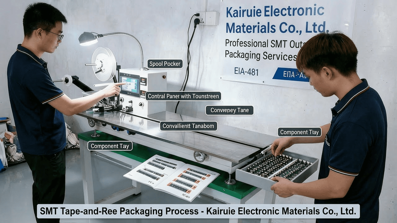
In the SMT packaging process, cover tape plays a critical role in securing components within carrier tape cavities during transportation, storage, and feeding. For sensitive IC chips, electrostatic discharge (ESD) protection is paramount to prevent latent damage or immediate failure. The 13-inch anti-static cover tape from Kairuie Electronic Materials Co., Ltd. offers a reliable solution, combining precise dimensional control with effective static dissipation. This article delves into the technical aspects of this product, covering material composition, process parameters, troubleshooting, quality standards, and selection guidance to help engineers optimize their packaging lines.
2. Product Structure & Material Composition
2.1 Layer Structure
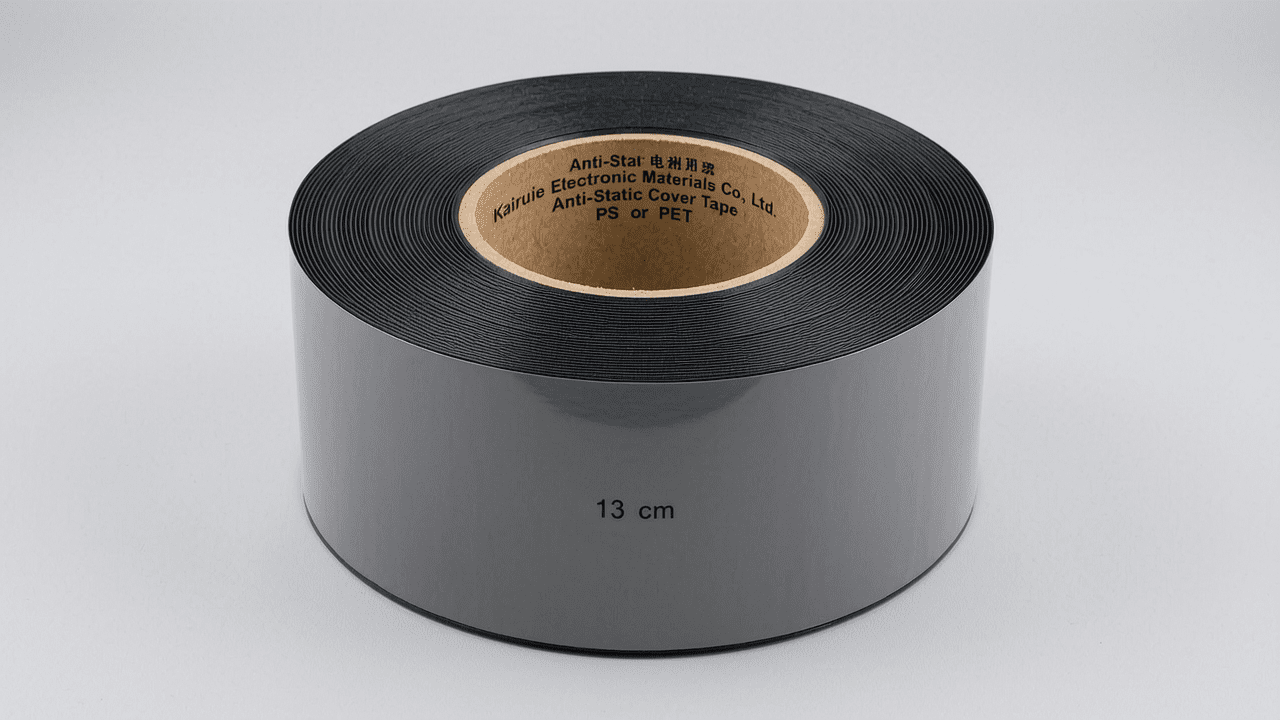
The 13-inch anti-static cover tape consists of three functional layers: a base film (typically PET), an anti-static coating, and a heat-sealable adhesive layer. The PET base provides mechanical strength and dimensional stability, while the anti-static layer ensures surface resistivity below 10^11 Ω/sq. The adhesive is formulated for consistent peel strength and clean removal.
2.2 Key Parameters
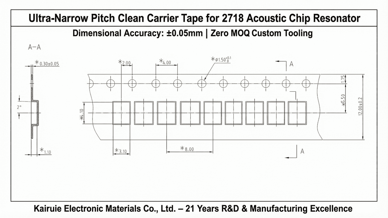
Available in 13-inch width, this tape comes in anti-static or non-anti-static versions, with colors including blue, black, clear, and pink. Standard lengths are 300 m/roll or 500 m/roll. The PET thickness ranges from 25 μm to 50 μm, and the adhesive type is heat-sealable, requiring a sealing temperature of 150–180°C for optimal bonding. Surface resistivity for anti-static variants is ≤10^11 Ω/sq.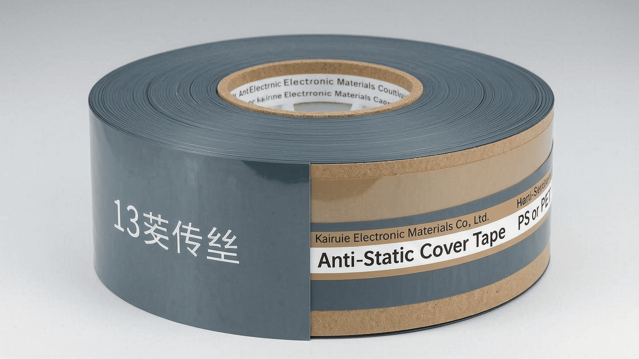
2.3 Product Models
Kairuie offers multiple models: PS (cost-effective for standard components), PC (high-temperature resistance up to 125°C), PET (up to 150°C), and PP (flexible for hardware parts). For IC chips, the recommended options are PS Anti-Static or PET Anti-Static, depending on temperature requirements.
3. Core Process Parameter Control
3.1 Temperature, Pressure, and Time
For heat-sealable cover tape, the recommended sealing temperature is 160–180°C, with a pressure of 2–4 bar and a dwell time of 0.3–0.5 seconds. These parameters ensure a peel strength of 0.3–0.8 N/cm, as per EIA-481 standard.
3.2 Impact on Quality
Insufficient temperature leads to weak adhesion and component loss during handling. Excessive temperature may cause adhesive residue or tape tearing. Optimal pressure ensures uniform bonding without crushing components. Process window optimization involves balancing these parameters to maintain consistent peel strength across the tape width.
3.3 Optimization Suggestions
For 13-inch wide tape, use a heated sealing head with uniform temperature distribution (±2°C). Perform peel tests at the start of each reel and adjust temperature in 5°C increments until target peel strength is achieved. For high-speed lines (>30K CPH), medium-temperature heat-sealable tape is recommended to reduce thermal stress on sensitive ICs.
4. Common Issues & Troubleshooting
| Symptom | Root Cause | Solution |
|---|---|---|
| Weak peel strength (<0.3 N/cm) | Sealing temperature too low or dwell time too short | Increase temperature by 5–10°C or extend dwell time by 0.1 s |
| Adhesive residue on tape or components | Excessive temperature or pressure | Reduce temperature by 5°C or lower pressure by 0.5 bar |
| Tape tearing during peeling | High peel strength or improper sealing head alignment | Check sealing head parallelism; reduce pressure if needed |
| Static discharge damage on ICs | Insufficient anti-static performance or grounding issues | Verify surface resistivity ≤10^11 Ω/sq; ensure proper grounding of equipment |
| Component rotation in cavity | Inadequate tape tension or incorrect carrier tape depth | Increase tape tension; verify cavity depth matches component height |
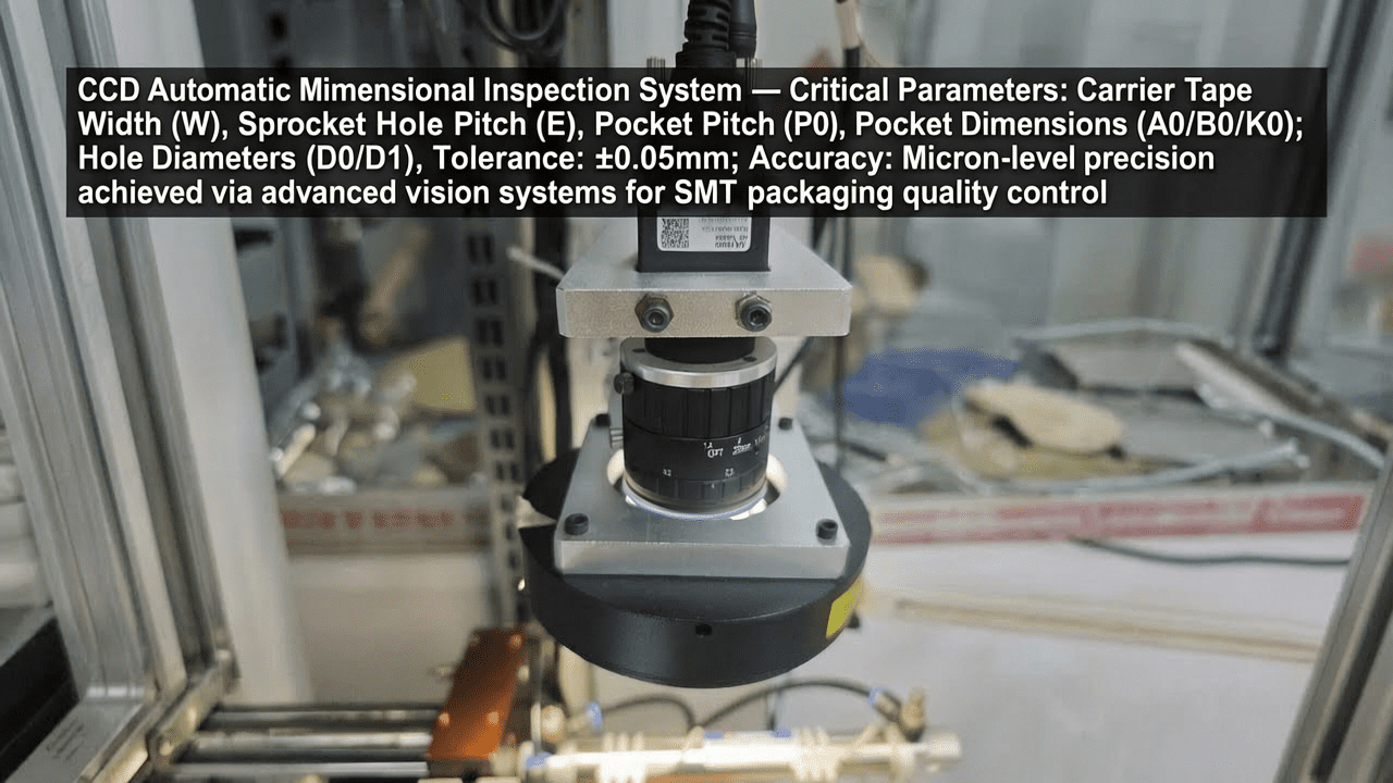
5. Quality Inspection Standards
5.1 Incoming Quality Control (IQC)
Visual inspection: no scratches, bubbles, or contamination. Dimensions: width tolerance ±0.3 mm, length per roll ±2%. Peel strength: test 3 samples per roll, average 0.3–0.8 N/cm. Surface resistivity: ≤10^11 Ω/sq for anti-static types.
5.2 In-Process Quality Control (IPQC)
Sampling frequency: one peel test every 100 m of tape. Acceptance criteria: peel strength within spec, no adhesive transfer. Visual check for wrinkles or misalignment.
5.3 Reliability Testing
Aging test: 85°C/85% RH for 168 hours, peel strength change <20%. High/low temperature test: -40°C to 85°C cycling, no delamination. Transportation simulation: vibration and drop tests per ISTA 2A.
6. Selection Guide
| Component Type | Recommended Cover Tape | Key Features |
|---|---|---|
| Standard ICs (non-ESD sensitive) | PS Non-Antistatic, Medium Tack | Cost-effective, good peel consistency |
| ESD-sensitive ICs (MOSFETs, logic chips) | PS Anti-Static or PET Anti-Static | Surface resistivity ≤10^11 Ω/sq, double-sided anti-static option |
| High-temperature ICs (125°C baking) | PC Anti-Static | Temperature resistance up to 125°C |
| Large connectors or deep cavities | Self-Adhesive High Tack or Heat-Sealable High Temperature | Strong adhesion, suitable for wide tapes (>37 mm) |
| High-speed placement (>30K CPH) | Heat-Sealable Medium Temperature | Fast sealing, stable peel |
7. Conclusion
The 13-inch anti-static cover tape from Kairuie Electronic Materials Co., Ltd. provides reliable ESD protection and process stability for IC chip packaging. With precise control of material composition, process parameters, and quality inspection, it ensures high yield in SMT assembly. Kairuie continues to innovate in electronic packaging materials, offering customized solutions for diverse applications. For more information, visit www.kairuie.com. We welcome industry peers to exchange ideas and collaborate on advancing packaging technology.