凯瑞尔电子材料
1. Introduction
In the field of SMT packaging, the compatibility between carrier tape and cover tape is crucial for ensuring the reliable transport and protection of electronic components during assembly. Polycarbonate (PC) carrier tapes, known for their excellent dimensional stability and temperature resistance, are widely used for high-reliability components such as QFN, BGA, and connectors. However, achieving a consistent seal requires the use of heat-activated adhesive (HAA) cover tapes specifically designed for PC substrates. This article delves into the technical aspects of PC carrier tape and heat-seal cover tape pairing, covering material composition, process parameter control, troubleshooting, quality inspection, and selection guidance. By the end, readers will gain a comprehensive understanding of how to optimize this packaging solution for maximum yield and reliability.
2. Product Structure & Material Composition
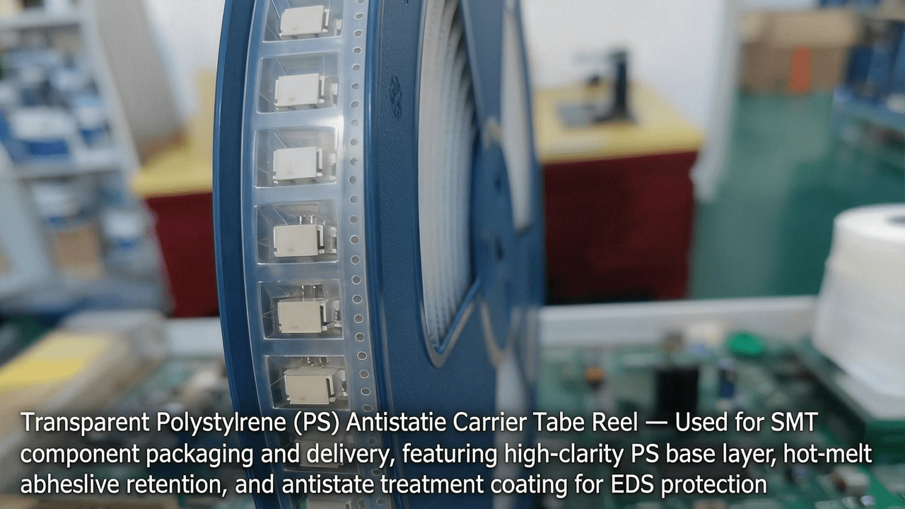
2.1 PC Carrier Tape Structure
PC carrier tape typically consists of a base polycarbonate layer with a thickness ranging from 0.30 mm to 0.50 mm, depending on component size and weight. The tape features embossed pockets formed by thermoforming, with precise dimensions to accommodate components. Key parameters include pocket depth tolerance (±0.05 mm), sprocket hole pitch (e.g., 4 mm, 8 mm, 12 mm), and camber (≤1 mm per 250 mm length). PC material offers high tensile strength (≥60 MPa) and a glass transition temperature of ~150°C, making it suitable for lead-free soldering processes.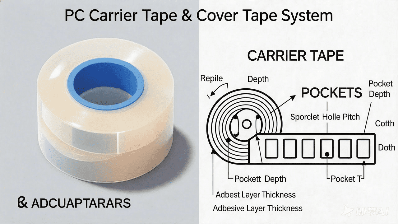
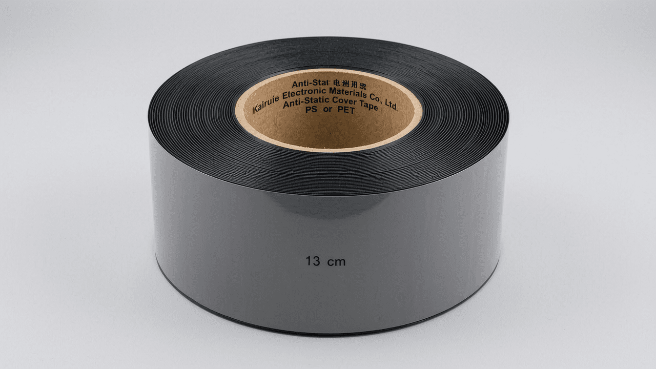
2.2 Heat-Seal Cover Tape Structure
Heat-activated cover tapes are multilayer structures comprising a polyester (PET) backing film (typically 12–25 μm thick), a heat-seal adhesive layer, and sometimes a static dissipative coating. The adhesive is formulated to activate at temperatures between 80°C and 120°C, forming a bond with the PC carrier. Surface resistivity is controlled to meet ESD requirements: static dissipative (10⁶–10¹¹ Ω/sq) or conductive (<10⁶ Ω/sq) for sensitive components. The peel strength after sealing is typically 0.1–0.6 N for 8 mm wide tape, adjustable by varying sealing parameters.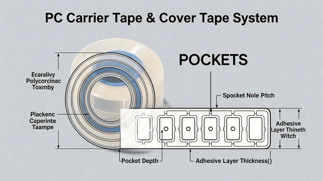
2.3 Kairuie Product Example
Kairuie Electronic Materials Co., Ltd. offers PC carrier tapes with thickness options of 0.35 mm and 0.45 mm, compatible with their HAA-800 series heat-seal cover tapes. The cover tape features a uniform adhesive coating with a thickness of 15±3 μm, ensuring consistent peel strength across the reel. The combination meets EIA-481 standards for leader/trailer lengths (minimum 400 mm leader, 150 mm trailer) and sprocket hole positioning.
3. Core Process Parameter Control
3.1 Temperature Settings
The sealing temperature for PC carrier tape with heat-seal cover tape should be maintained between 90°C and 110°C. Lower temperatures (<80°C) result in insufficient adhesion, while higher temperatures (>120°C) may cause tape shrinkage or deformation of PC pockets. The optimal temperature is typically 100°C, verified by peel strength tests. For Kairuie HAA-800 cover tape, the recommended sealing temperature range is 95–105°C.
3.2 Pressure and Time
Sealing pressure should be set between 1.5 and 3.0 kg/cm², with a dwell time of 0.5 to 1.5 seconds. Higher pressure improves adhesive flow but may cause excessive compression of the carrier tape. A common starting point is 2.0 kg/cm² for 1.0 second. The pressure must be uniform across the sealing head to avoid weak spots. Adjustments should be made based on tape width: wider tapes (e.g., 24 mm) require higher pressure (up to 3.0 kg/cm²) to ensure full contact.
3.3 Process Window Optimization
To achieve consistent peel strength, maintain the sealing head temperature within ±2°C of the set point. Use a thermal profiler to verify the actual temperature on the tape surface. The peel strength should fall within 0.2–0.5 N for 8 mm wide tape. If peel strength is too high, reduce temperature or pressure; if too low, increase temperature or dwell time. Regular calibration of the sealing machine is essential.
4. Common Issues & Troubleshooting
| Symptom | Root Cause | Solution |
|---|---|---|
| Cover tape lifts off during feeding | Insufficient sealing temperature or pressure | Increase temperature to 100°C and pressure to 2.5 kg/cm²; check heater uniformity |
| Peel strength too high (>0.6 N) | Excessive temperature or dwell time | Reduce temperature to 95°C or dwell time to 0.8 s; verify adhesive type |
| Cover tape wrinkles after sealing | Uneven pressure or tape misalignment | Realign tape guides; clean sealing head; reduce pressure slightly |
| Component shift in pocket | Pocket depth mismatch or excessive vibration | Verify pocket dimensions; adjust vacuum hold-down during sealing |
| Static discharge during peeling | Inadequate ESD protection | Use static dissipative cover tape (10⁶–10¹¹ Ω/sq); ground equipment |
5. Quality Inspection Standards
5.1 Incoming Quality Control (IQC)
Upon receiving PC carrier tape and heat-seal cover tape, inspect visual defects (scratches, contamination, bowing). Measure carrier tape dimensions: pocket depth, width, and sprocket hole pitch using a calibrated optical comparator. For cover tape, check adhesive coating uniformity and surface resistivity. Peel strength test on a sample sealed under standard conditions (100°C, 2.0 kg/cm², 1.0 s) should yield 0.2–0.5 N for 8 mm width.
5.2 In-Process Quality Control (IPQC)
During production, sample every 30 minutes or per reel change. Measure peel strength at three positions (start, middle, end) to ensure consistency. Acceptance criteria: peel strength within ±0.1 N of target. Also inspect for cover tape alignment (no offset >0.5 mm) and pocket integrity. Record temperature and pressure readings for traceability.
5.3 Reliability Testing
Perform aging test: store sealed reels at 85°C/85% RH for 168 hours, then check peel strength (should remain within 80% of initial). High/low temperature cycle: -40°C to +85°C, 10 cycles, inspect for delamination. Transportation simulation: vibration test per ISTA 2A, verify no component loss or cover tape opening.
6. Selection Guide
| Component Type | Recommended Carrier Tape | Cover Tape | Key Parameters |
|---|---|---|---|
| Passive (0402, 0603) | PS carrier (paper or embossed) | Pressure-sensitive (PSA) | Peel strength 0.1–0.3 N; ESD: antistatic |
| IC (SOIC, QFP) | PC carrier (0.35 mm thick) | Heat-seal (HAA-800) | Peel strength 0.3–0.6 N; static dissipative |
| Connector (large pitch) | PC carrier (0.45 mm thick) | Heat-seal (HAA-800) | Peel strength 0.4–0.8 N; conductive option |
| LED (sensitive) | PC carrier (anti-static) | Heat-seal (low outgas) | Peel strength 0.2–0.4 N; low ionic contamination |
For high-temperature processes (e.g., lead-free reflow), PC carrier tapes are preferred due to their thermal stability. Heat-seal cover tapes offer better sealing integrity than PSA tapes for large components. Kairuie provides custom solutions based on component dimensions and ESD requirements.
7. Conclusion
The combination of PC carrier tape and heat-seal cover tape is a robust solution for SMT packaging, offering excellent dimensional accuracy, temperature resistance, and seal reliability. By understanding the material composition, optimizing process parameters, and implementing rigorous quality controls, manufacturers can minimize defects and improve assembly yield. Kairuie Electronic Materials Co., Ltd. is committed to providing high-quality PC carrier tapes and matching heat-seal cover tapes, backed by technical support and customization services. For more information, visit www.kairuie.com. We welcome industry peers to exchange ideas and explore innovative packaging solutions together.