凯瑞尔电子材料
1. Introduction
1.1 The Critical Role of Carrier Tape Reels in SMT Packaging
In surface mount technology (SMT) packaging, the plastic reel is not merely a passive container for carrier tape; it is a precision logistics component that directly influences tape feeding accuracy, component protection, and overall production efficiency. Carrier tape reels, commonly available in 7-inch, 13-inch, and 15-inch diameters, must be selected carefully to match the carrier tape width, pocket depth, component size, and pick-and-place machine requirements. Kairuie Electronic Materials Co., Ltd. supplies high-precision plastic reels designed for SMT electronic packaging materials, supporting carrier tape widths from 8 mm up to 200 mm, as mentioned in our pricing inquiry guide. A mismatched reel can cause tape jamming, telescoping, excessive reel changeovers, or insufficient tape length per reel, leading to production downtime. This article provides technical guidance on selecting the appropriate reel diameter, calculating carrier tape length capacity, and implementing quality control measures to ensure stable SMT packaging operations.
1.2 Technical Topics Covered
This article will address seven key areas: the structural and material composition of standard 7-inch, 13-inch, and 15-inch plastic reels; core process parameters such as winding tension, speed, and environmental conditions; common reel-related issues and troubleshooting methods; quality inspection standards for incoming, in-process, and reliability testing; a practical selection guide based on component type and carrier tape width; and a conclusion summarizing the value of Kairuie’s reel solutions. Throughout the article, specific formulas and examples are provided to calculate how many meters of carrier tape can be wound onto each reel size, enabling engineers and purchasing managers to make informed decisions.
2. Product Structure & Material Composition
2.1 Reel Dimensional Standards and Material Grades
Plastic reels for carrier tape are typically injection-molded from polystyrene (PS), polycarbonate (PC), or acrylonitrile butadiene styrene (ABS). For standard SMT applications, PS is most common due to its balance of rigidity, static dissipation, and cost. Kairuie’s plastic reels are manufactured to EIA-481 standards, with the following reference dimensions for the three most common diameters: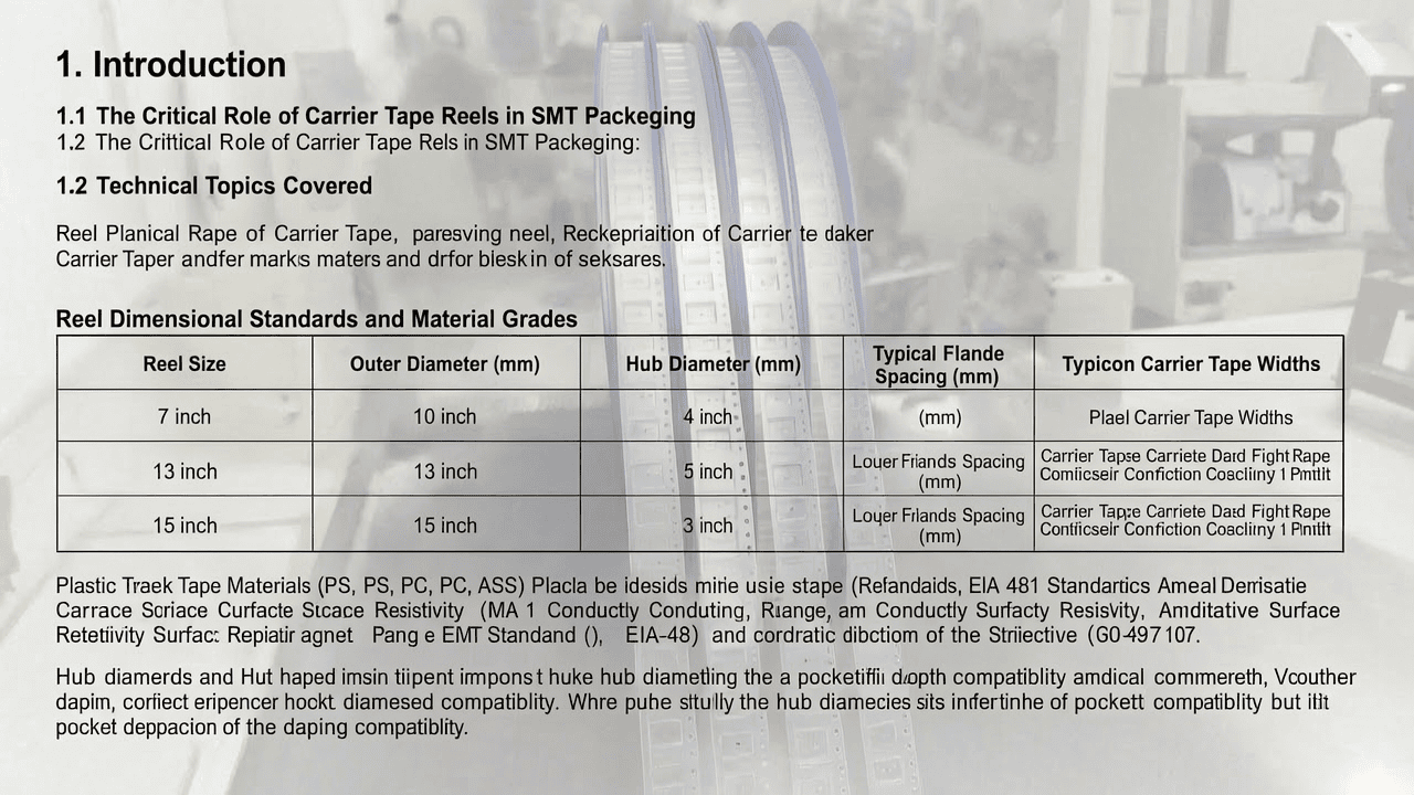
| Reel Size | Outer Diameter (mm) | Hub Diameter (mm) | Typical Flange Spacing (mm) | Common Carrier Tape Widths |
|---|---|---|---|---|
| 7 inch | 178 | 60 | 8 – 24 | 8, 12, 16, 24 mm |
| 13 inch | 330 | 100 | 8 – 56 | 8, 12, 16, 24, 32, 44, 56 mm |
| 15 inch | 381 | 100 | 8 – 72 | 8, 12, 16, 24, 32, 44, 56, 72 mm |
For large tape formats, Kairuie can supply reels with outer diameters up to 15 inches and flange spacings accommodating carrier tape widths of 104 mm, 120 mm, and even 200 mm, as specified in the pricing inquiry guide. The hub diameter is critical because it determines the minimum bending radius of the carrier tape; a smaller hub may cause excessive stress on embossed pockets or cracking of the base film. The flange spacing must be at least 0.5–1.0 mm wider than the carrier tape to allow smooth winding without edge damage.
Material composition also affects antistatic performance. Kairuie offers standard antistatic (10^6–10^9 ohms/square surface resistivity) and conductive (10^3–10^5 ohms/square) reel options to prevent electrostatic discharge (ESD) damage to sensitive components. For high-temperature or harsh environments, polycarbonate reels provide better dimensional stability up to 120°C, whereas PS is limited to about 70°C.
2.2 Adhesive and Surface Treatment Considerations
Although plastic reels themselves do not have an adhesive layer, the carrier tape wound onto them often has a cover tape with pressure-sensitive adhesive (PSA). The reel’s inner surface finish and flange design must be compatible with the cover tape’s adhesive to avoid sticking or delamination during unwinding. Kairuie applies a controlled surface texture on flange inner walls to reduce friction while preventing tape slippage. For embossed carrier tapes with deep pockets, the reel hub diameter should be sufficiently large to prevent pocket crushing; a 7-inch reel with a 60 mm hub is typically unsuitable for pocket depths greater than 3 mm, whereas a 13-inch or 15-inch reel with a 100 mm hub is recommended.
Surface resistivity values for the reel material should be specified: antistatic reels between 10^6 and 10^9 ohms/square, and conductive reels between 10^3 and 10^5 ohms/square. These parameters prevent charge accumulation during high-speed winding and unwinding. Kairuie’s reels are also available with UV stabilizers for cleanroom compatibility and low outgassing properties for sensitive optical or MEMS components.
3. Core Process Parameter Control
3.1 Reel Winding Tension and Speed Control
Proper winding tension is essential to ensure that carrier tape is uniformly wound without stretching, pocket deformation, or telescoping. Recommended winding tension ranges depend on carrier tape width and base film thickness. For standard 8 mm to 24 mm polycarbonate or polystyrene carrier tape, winding tension should be maintained between 0.5 N and 2.0 N. For wider tapes (32 mm to 72 mm) or tapes with deep pockets, tension may need to be increased to 2.0–5.0 N to maintain tight winding. However, excessive tension can crush embossed pockets or cause the cover tape to shift. Kairuie recommends starting at the lower end of the range and gradually increasing until the reel is firm but not distorted.
Winding speed also affects quality: typical speeds range from 50 to 300 revolutions per minute (RPM) depending on reel diameter. For a 7-inch reel, maximum winding speed should not exceed 200 RPM to avoid vibration and uneven layering. For 13-inch and 15-inch reels, speeds up to 150 RPM are recommended due to higher inertia. Process optimization should include a deceleration profile near the end of the reel to prevent overshoot and tape damage.
3.2 Temperature and Humidity Effects on Tape Length
Environmental conditions during storage and winding significantly affect carrier tape dimensions. Polystyrene and polycarbonate films expand with temperature; a change of 10°C can alter tape width by approximately 0.05–0.1 mm. High humidity may cause the paper or cardboard core (if used) to swell, affecting the effective hub diameter. Kairuie recommends maintaining a controlled environment of 23 ± 5°C and 40–60% relative humidity for winding operations and reel storage. These conditions minimize dimensional variations and ensure consistent tape length calculations.
To calculate the maximum tape length that can be wound on a reel, use the formula for spiral winding:
L = [π × (D² – d²)] / (4 × t)
Where:
L = tape length (mm)
D = outer diameter of wound tape (mm) – typically reel outer diameter minus flange clearance (2–5 mm)
d = hub diameter (mm)
t = effective thickness of one layer of carrier tape (mm), including pocket height and base film thickness.
For example, for a 7-inch reel (D = 170 mm effective, d = 60 mm, t = 1.2 mm), L = [π × (170² – 60²)] / (4 × 1.2) = [π × (28900 – 3600)] / 4.8 = (π × 25300) / 4.8 ≈ 16552 mm ≈ 16.6 meters. For a 13-inch reel (D = 320 mm, d = 100 mm, t = 1.2 mm), L = [π × (320² – 100²)] / 4.8 = (π × (102400 – 10000)) / 4.8 ≈ (π × 92400)/4.8 ≈ 60476 mm ≈ 60.5 meters. For a 15-inch reel (D = 370 mm, d = 100 mm, t = 1.2 mm), L = [π × (370² – 100²)] / 4.8 = (π × (136900 – 10000))/4.8 ≈ (π × 126900)/4.8 ≈ 83053 mm ≈ 83.1 meters. These lengths are typical for 8 mm carrier tape with 1.1 mm pocket depth and 0.1 mm base film, giving effective t ≈ 1.2 mm. Thicker tapes reduce length proportionally.
3.3 Process Window Optimization Suggestions
To optimize the winding process, Kairuie recommends establishing a design of experiments (DOE) with tension, speed, and ambient humidity as factors. The acceptance criteria should include no visible tape deformation, consistent flange-to-tape clearance, and a reel weight within ±5% of theoretical. For automated SMT lines, reel changeover time is a critical cost factor; selecting a larger reel (13-inch or 15-inch) can reduce changeovers by 3–5 times compared to a 7-inch reel for the same carrier tape, improving machine utilization. However, larger reels require more floor space and may not fit all feeder systems, so the process window must include feeder compatibility checks.
4. Common Issues & Troubleshooting
4.1 Typical Reel-Related Process Failures
The following table summarizes five common problems encountered with carrier tape reels in SMT packaging, along with their root causes and recommended solutions.
| Symptom | Root Cause | Solution |
|---|---|---|
| Tape telescoping (sideways slippage) | Insufficient winding tension or excessive flange clearance | Increase tension to 1.5–3.0 N; use reel with flange spacing only 0.5 mm wider than tape |
| Carrier tape jamming in feeder | Reel hub diameter too small causing excessive curvature | Switch to 13-inch or 15-inch reel with 100 mm hub; verify pocket depth compatibility |
| Cover tape lifting or delamination | Adhesive incompatibility with reel surface or high humidity | Use reel with controlled surface roughness; store at 40–60% RH; test adhesion on reel flange |
| Insufficient tape length per reel | Effective tape thickness underestimated; reel outer diameter not fully utilized | Recalculate using actual t; use larger reel or reduce pocket depth design |
| Static discharge damaging components | Reel surface resistivity too high (>10^12 ohms/square) | Use antistatic or conductive reel (10^3–10^9 ohms/square) and ground winding equipment |
In addition to these, edge damage to carrier tape can occur if the flange inner surface has burrs or sharp edges. Kairuie performs 100% visual inspection of flange edges before shipment to ensure smooth, burr-free surfaces. For high-speed operations, periodic monitoring of reel runout is recommended; radial runout should not exceed 0.5 mm for 7-inch reels and 1.0 mm for 13/15-inch reels.
5. Quality Inspection Standards
5.1 Incoming Quality Control (IQC)
At incoming inspection, plastic reels should be checked for visual defects such as cracks, warpage, flash, and contamination. Dimensional verification includes outer diameter, hub diameter, flange spacing, and flange thickness using calibrated calipers or a coordinate measuring machine. Peel strength of any adhesive labels or tape retention features, if present, should be tested per ASTM D3330. Surface resistivity should be measured using a concentric ring probe per ASTM D257, with acceptance criteria of 10^6–10^9 ohms/square for antistatic and 10^3–10^5 ohms/square for conductive reels. Kairuie provides certificates of conformance with each batch, including material grade and resistivity values.
5.2 In-Process Quality Control (IPQC)
During winding operations, sampling frequency should be at least one reel per every 50 reels produced or once per shift, whichever is more frequent. Acceptance criteria include: no visible tape telescoping (lateral offset < 0.3 mm), reel weight within ±3% of theoretical value, and flange parallelism within 0.2 mm. Winding tension should be monitored in real time and recorded on control charts. If any reel fails, the process should be halted and the previous five reels quarantined for 100% inspection. Kairuie’s IPQC protocols also include check of cover tape peel force on the reel, which should remain within the tape manufacturer’s specification (typically 20–100 gf).
5.3 Reliability Testing
Reliability testing for reeled carrier tape assemblies includes thermal cycling, aging, and transportation simulation. Aging test: expose reel to 60°C at 85% RH for 168 hours, then verify no dimensional change greater than 0.2% and no degradation of antistatic properties. High/low temperature test: cycle between -40°C and +85°C for 100 cycles; after test, carrier tape must unwinding smoothly without cracking. Transportation simulation: perform random vibration test per ISTA 2A for 60 minutes; after test, reel must show no deformation and tape must remain securely wound. Kairuie’s reels are designed to pass these tests when paired with compatible carrier tape, providing confidence for global logistics.
6. Selection Guide
6.1 Matching Reel Size to Component Type and Carrier Tape Width
Choosing the correct reel diameter depends primarily on component type, carrier tape width, pocket depth, and production batch size. For small passive components such as 0201, 0402, and 0603 resistors and capacitors, 8 mm carrier tape on a 7-inch reel is standard; typical capacity is 4,000 to 10,000 components per reel depending on pitch. For small outline transistors (SOT) and small ICs, 12 mm or 16 mm tape on 7-inch reels is common for prototyping, but 13-inch reels are preferred for mass production to reduce changeovers. For larger ICs (QFP, BGA) and connectors, 24 mm to 44 mm carrier tape on 13-inch reels provides sufficient capacity, while 15-inch reels are used for very high volume or wide tapes (56 mm, 72 mm). For special large tape formats up to 104 mm, 120 mm, or 200 mm, Kairuie provides custom reel solutions as described in the pricing inquiry guide.
| Application Scenario | Typical Component Type | Carrier Tape Width | Recommended Reel Size | Approx. Tape Length (t=1.2mm) |
|---|---|---|---|---|
| Prototyping / low volume | 0201–0603 passives | 8 mm | 7 inch | ~16 m |
| High-volume passives | 0402–0805 resistors/caps | 8 mm | 13 inch | ~60 m |
| Small ICs / transistors | SOT-23, SOT-89 | 12 mm | 7 or 13 inch | 7 inch: ~15 m; 13 inch: ~55 m |
| Medium ICs | SOIC, TSSOP | 16 mm / 24 mm | 13 inch | 16 mm: ~55 m; 24 mm: ~50 m |
| Large ICs / connectors | QFP, BGA, FPC connectors | 32–44 mm | 13 or 15 inch | 13 inch: ~45 m; 15 inch: ~65 m |
| Very wide / heavy components | Power modules, large connectors | 56–72 mm | 15 inch | ~60–70 m |
| Custom large format | Special modules, LED arrays | 104–200 mm | Custom >15 inch or special hub | Contact Kairuie |
For tape thickness different from 1.2 mm, use the formula provided in Section 3.2 to recalculate. Kairuie’s technical team can assist with reel selection based on your specific carrier tape design, pocket depth, and production capacity requirements, as listed in our pricing inquiry guide (component type, dimensions, tape width, capacity, feeding method, etc.).
7. Conclusion
7.1 Summary of Core Value and Company Invitation
Selecting the correct plastic reel—7-inch, 13-inch, or 15-inch—is a critical decision that balances tape capacity, component protection, feeder compatibility, and total cost of ownership. Kairuie Electronic Materials Co., Ltd. provides high-precision plastic reels manufactured to EIA-481 standards, with antistatic and conductive options, dimensional accuracy within ±0.2 mm, and support for carrier tape widths from 8 mm up to 200 mm. Our reels are engineered to ensure stable unwinding, minimize component damage, and reduce production downtime. By following the process parameter control, troubleshooting, and quality inspection standards outlined in this article, SMT manufacturers can optimize their packaging operations and achieve higher yields. We invite industry peers and technical experts to exchange ideas and explore customized solutions. For more information or to request a quotation, please visit our website at www.kairuie.com. Our team is ready to support your carrier tape and reel requirements with professional technical consultation and competitive pricing.


