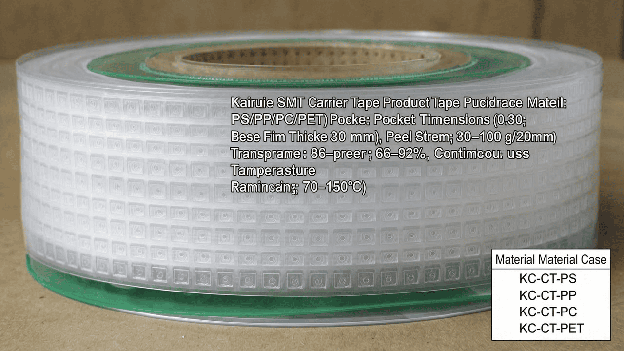
凯瑞尔电子材料
1. Introduction
In surface mount technology (SMT), carrier tape is the backbone of automated component handling, feeding, and placement. It protects sensitive electronic components from mechanical damage, electrostatic discharge (ESD), and contamination during transportation and high-speed pick-and-place operations. Among the many design decisions, the choice of carrier tape base material—PS, PP, PC, or PET—directly impacts pocket dimensional stability, peel strength, transparency, and cost efficiency. Kairuie Electronic Materials Co., Ltd. specializes in precision SMT electronic packaging materials and offers a complete portfolio of carrier tapes manufactured from these four thermoplastic films. This article provides a detailed technical comparison of PS, PP, PC, and PET carrier tapes, covering material structure, process parameters, troubleshooting, quality standards, and application-specific selection guidance. Specific product models, such as the Kairuie KC-CT-PS series, KC-CT-PP series, KC-CT-PC series, and KC-CT-PET series, are referenced to illustrate real-world engineering choices.
2. Product Structure & Material Composition
2.1 Layer Structure and Functional Coatings
All Kairuie carrier tapes share a three-layer construction: base film, adhesive layer, and optional surface treatment layer. The base film is the primary mechanical carrier, typically extruded or calendered from PS, PP, PC, or PET resin. Kairuie’s standard base film thickness is 0.30 mm ±0.02 mm for general-purpose tapes, with heavy-duty versions available at 0.40 mm and 0.50 mm. For ultra-thin profiles used in compact modules, 0.20 mm film is also offered. The adhesive layer is a heat-sealable coating, usually an acrylic or EVA-based formulation, applied to the sealing ledge of the carrier tape. Kairuie’s KC-CT-PS series uses a low-temperature acrylic adhesive with a sealing window of 120–160°C, while the KC-CT-PET series employs a high-temperature polyester adhesive for sealing at 160–200°C. The optional surface treatment layer includes anti-static coatings that achieve surface resistivity of 10^5–10^9 ohms/sq, and in some grades, a conductive carbon coating for 10^3–10^5 ohms/sq. This layered design ensures that the carrier tape maintains pocket integrity during thermoforming, high-speed indexing, and cover tape sealing.
2.2 Key Material Parameters of PS, PP, PC, PET
The following table summarizes the primary technical parameters for Kairuie’s four carrier tape material families. All values are typical for 0.30 mm base film unless otherwise noted.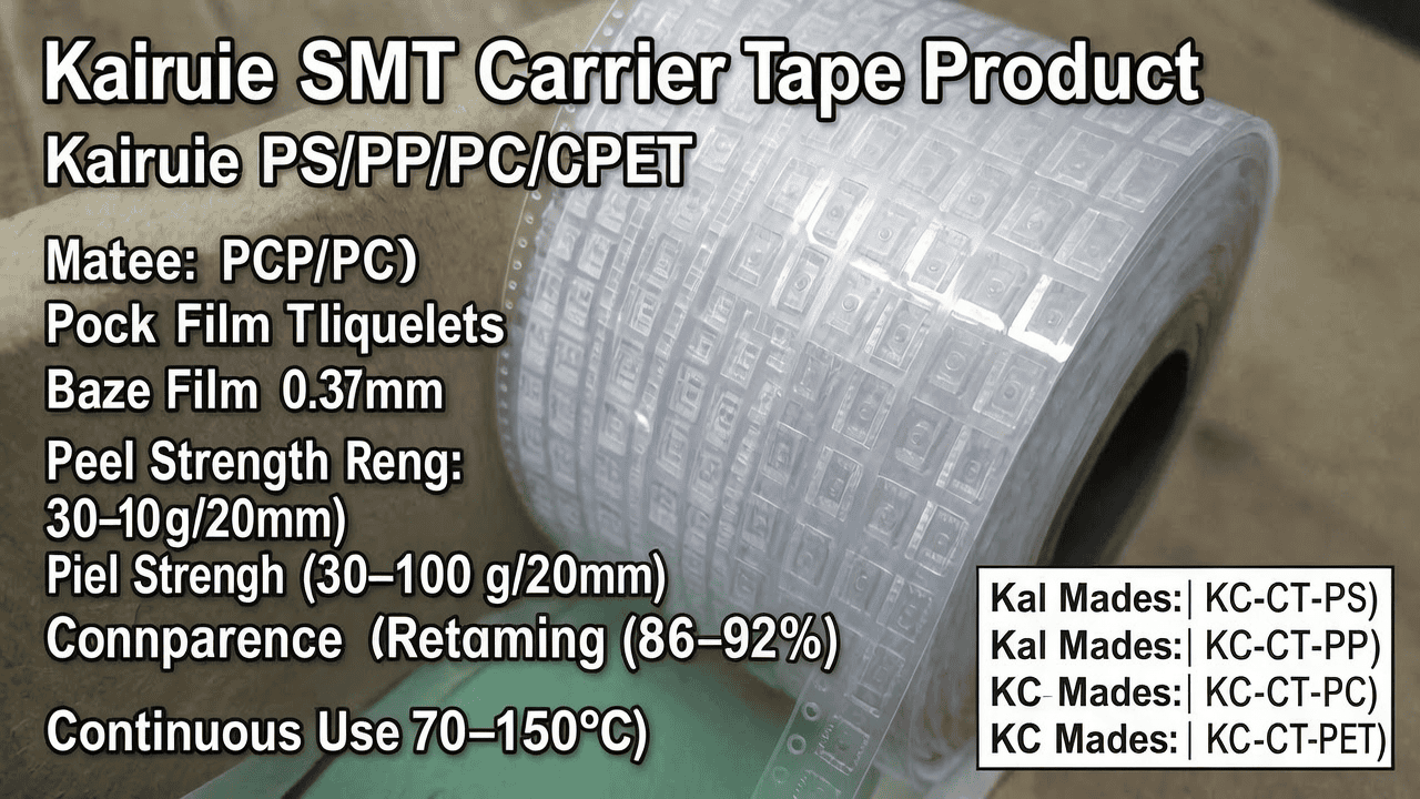
| Parameter | KC-CT-PS Series | KC-CT-PP Series | KC-CT-PC Series | KC-CT-PET Series |
|---|---|---|---|---|
| Base material | Polystyrene | Polypropylene | Polycarbonate | Polyethylene terephthalate |
| Film thickness range (mm) | 0.20–0.50 | 0.20–0.50 | 0.25–0.50 | 0.20–0.50 |
| Density (g/cm³) | 1.05 | 0.90 | 1.20 | 1.38 |
| Continuous use temp (°C) | 70 | 90 | 120 | 150 |
| Surface resistivity (ohms/sq) | 10^6–10^9 | 10^6–10^9 | 10^6–10^9 | 10^4–10^8 |
| Transparency (%) | 88–92 | 80–85 | 89–91 | 86–90 |
| Pocket forming temp (°C) | 100–120 | 120–140 | 140–170 | 120–160 |
| Peel strength (g/20mm) | 30–60 | 25–55 | 40–80 | 50–100 |
PS offers excellent clarity and rigidity at the lowest cost, making it ideal for small passive components. PP provides superior chemical resistance and flexibility, suitable for components with delicate leads. PC delivers high impact strength and dimensional stability at elevated temperatures, preferred for power devices and connectors. PET balances heat resistance, mechanical strength, and cost, and is the most widely used material in high-volume SMT production. Kairuie’s anti-static treatment uses a proprietary surfactant-free coating that maintains stable surface resistivity even after 1,000 hours of thermal aging at 85°C/85% RH.
3. Core Process Parameter Control
3.1 Temperature Control Parameters
Precise temperature control during pocket forming and cover tape sealing is critical. Each carrier tape material has a specific thermoforming temperature window. For Kairuie KC-CT-PS, the recommended pocket forming temperature is 105–115°C. Below 100°C, the PS film does not soften sufficiently, resulting in shallow pockets or micro-cracks; above 120°C, excessive flow can cause pocket wall thinning beyond the acceptable 20% reduction limit. KC-CT-PP requires 125–135°C; PP has a narrower processing window due to its semi-crystalline nature, so temperature uniformity of ±3°C across the mold is essential. KC-CT-PC needs 150–165°C, and mold preheating to 120°C is recommended to avoid stress whitening. KC-CT-PET operates at 130–150°C, but its crystallinity means that cooling rate after forming must be controlled at 5–10°C/sec to prevent dimensional rebound. For cover tape sealing, the heat-sealing bar temperature should be set 20–30°C above the adhesive activation temperature: 120–140°C for PS and PP tapes, 160–180°C for PC, and 180–200°C for PET. Tight temperature control ensures consistent peel strength within ±10 g/20mm of nominal value.
3.2 Pressure and Dwell Time Optimization
Pressure and dwell time influence pocket dimensional accuracy and sealing integrity. Kairuie recommends a forming pressure of 2–4 kg/cm² for PS and PP, and 3–5 kg/cm² for PC and PET. Higher pressure improves pocket corner definition but increases the risk of film thinning; the minimum pocket corner radius should be maintained at 0.2 mm for component lead clearance. Dwell time in the forming station is typically 0.5–1.2 seconds for thin films (0.20–0.30 mm) and 1.0–2.0 seconds for thick films (0.40–0.50 mm). For cover tape sealing, the recommended pressure is 1.5–3.0 kg/cm² with a dwell time of 0.3–0.8 seconds. A process capability study on Kairuie KC-CT-PET 0.30 mm tape showed that when sealing pressure was increased from 1.0 to 2.5 kg/cm², peel strength rose from 35 to 72 g/20mm, but beyond 3.0 kg/cm², the adhesive began to squeeze out and contaminate the sealing ledge. Therefore, process engineers should perform design of experiments (DOE) to lock the optimal parameter window. Kairuie provides a process parameter checklist with each reel, including recommended forming temperature, sealing temperature, sealing pressure, and dwell time for the specific material and pocket geometry.
4. Common Issues & Troubleshooting
4.1 Typical Defect Analysis and Solutions
The following table lists five common carrier tape problems encountered in SMT production, along with root causes and corrective actions based on Kairuie’s field service data.
| Symptom | Root Cause | Solution |
|---|---|---|
| Pocket deformation or collapse during reeling | Insufficient base film thickness or forming temperature too high for rigid materials like PS | Increase film thickness to 0.40 mm; lower forming temperature by 5–10°C; verify pocket depth-to-width ratio ≤1:1.5 |
| Excessive or inconsistent peel strength | Sealing temperature/pressure variation; adhesive aging | Recalibrate sealing bar temperature to ±2°C; set sealing pressure to 2.0 kg/cm²; replace cover tape or use Kairuie’s heat-sealable cover tape matched to same material family |
| Static damage to components | Surface resistivity out of spec due to anti-static coating wear | Use Kairuie’s conductive carrier tape (10^3–10^5 ohms/sq); verify grounding of processing equipment; avoid humidity below 30% RH |
| Pocket dimensional deviation beyond ±0.1 mm | Mold misalignment or film shrinkage after forming | Check mold tooling for wear; adjust cooling rate to 5°C/sec for PET; use PC material for high-precision applications requiring ±0.05 mm |
| Cover tape lifting or component fallout | Insufficient sealing dwell time or contamination on sealing ledge | Increase dwell time to 0.5–0.8 sec; clean sealing bar daily with isopropyl alcohol; verify cover tape width matches carrier tape ledge width |
These troubleshooting steps are part of Kairuie’s 8D problem-solving support. For each lot, the company retains process data for 24 months, enabling rapid root cause identification and corrective action implementation.
5. Quality Inspection Standards
5.1 Incoming Quality Control (IQC)
Kairuie implements stringent IQC for all raw film and finished carrier tape. Incoming film is inspected for visual defects such as gels, fisheyes, and scratches under 1,000-lux illumination with a 3x magnifier. Film thickness is measured at five points across the width using a digital micrometer with 0.001 mm resolution; total thickness variation (TTV) must not exceed ±5% of nominal. Peel strength of the adhesive layer is tested per EIA-481-D using a 180° peel test at 300 mm/min; acceptance criteria are material-specific: PS 30–60 g/20mm, PP 25–55 g/20mm, PC 40–80 g/20mm, PET 50–100 g/20mm. Surface resistivity is verified using a concentric ring probe at 100V DC; values must fall within the specified decade range. Dimensional checks include pocket length, width, depth, and pitch, with a sampling plan of ANSI/ASQ Z1.4 Level II, AQL 0.65 for critical dimensions and AQL 1.0 for minor dimensions.
5.2 In-Process Quality Control (IPQC)
During carrier tape manufacturing, Kairuie performs IPQC inspections every 2 hours or every 5,000 meters, whichever comes first. Operators measure pocket dimensions on five consecutive pockets using a vision measurement system with 0.01 mm accuracy. Peel strength is tested on one sample per production lot using a tensile tester. Surface resistivity is checked on three positions per reel (leading, middle, trailing). If any parameter falls outside the control limit, the production line is stopped and the affected material is quarantined. Statistical process control (SPC) charts are maintained for pocket depth and peel strength, with process capability indices Cpk ≥ 1.33 required for all critical parameters. Kairuie’s cleanroom environment for carrier tape conversion is ISO Class 8, minimizing particle contamination that could affect component adhesion.
5.3 Reliability Testing
Kairuie conducts a battery of reliability tests to ensure long-term performance. Thermal aging is performed at 85°C for 1,000 hours, after which peel strength must retain at least 80% of initial value and surface resistivity must not drift by more than one decade. High/low temperature cycling from -40°C to +85°C for 500 cycles is used for PC and PET materials to verify resistance to stress cracking. Transportation simulation follows ISTA 2A, including random vibration at 1.0 Grms for 2 hours and drop tests from 760 mm height. After simulation, pocket deformation must be less than 0.1 mm and no component fallout is allowed. For humid environments, a 85°C/85% RH test for 500 hours is performed on anti-static grades to confirm that the surfactant-free conductive coating does not wash out. All test reports are available to customers upon request, and Kairuie’s quality management system is certified to ISO 9001:2015 and IATF 16949:2016.
6. Selection Guide
6.1 Component Type Recommendations
The choice of carrier tape material should start with the component type, package size, and required protection level. The table below provides Kairuie’s recommended material series for common SMT component categories.
| Component Type | Typical Package Size | Recommended Material | Kairuie Series | Key Reason |
|---|---|---|---|---|
| Passive chip resistors/capacitors (0201–0805) | 0.6×0.3 mm to 2.0×1.2 mm | PS | KC-CT-PS | Low cost, high clarity for vision inspection, adequate rigidity for small pockets |
| LEDs and optical sensors | 1.6×0.8 mm to 3.5×2.8 mm | PC or PET | KC-CT-PC / KC-CT-PET | High transparency, heat resistance during reflow, dimensional stability |
| Transistors, diodes, small ICs (SOT, SOD, QFN) | 1.0×0.6 mm to 5.0×5.0 mm | PET | KC-CT-PET | Excellent balance of strength, heat resistance, and cost for high-speed assembly |
| Power devices, connectors, shielded modules | 5.0×5.0 mm to 15×15 mm | PC | KC-CT-PC | High impact strength and resistance to pocket deformation with heavy components |
| High-frequency or flexible components | Irregular shapes | PP | KC-CT-PP | Chemical resistance and flexibility reduce lead damage; lower static charge generation |
6.2 Application Scenario Comparison
Beyond component type, production environment and logistics conditions influence material selection. The following table compares the four materials across eight critical application scenarios.
| Scenario | PS | PP | PC | PET |
|---|---|---|---|---|
| High-volume passive placement | Best choice | Acceptable | Over-specified | Acceptable |
| High-temperature reflow (260°C peak) | Not recommended | Limited | Good | Excellent |
| Long-distance sea freight with humidity | Poor | Good | Good | Excellent |
| ESD-sensitive components | Good (anti-static) | Excellent (low tribocharge) | Good | Excellent |
| Heavy components over 10 grams | Poor | Fair | Excellent | Good |
| Optical inspection clarity requirement | Excellent | Fair (haze) | Excellent | Very good |
| Cleanroom compatibility (low particle) | Good | Good | Excellent | Excellent |
| Cost per meter (relative index) | 1.0 | 1.2 | 2.5 | 1.8 |
For most standard SMT applications, PET offers the best overall value. However, when ultra-low cost is paramount and components are small, PS is the logical choice. PC is reserved for high-reliability or heavy-component scenarios, while PP serves niche applications requiring chemical inertness or low electrostatic attraction.
7. Conclusion
Selecting the right carrier tape material—PS, PP, PC, or PET—is a critical decision that affects SMT production yield, component protection, and total cost of ownership. Kairuie Electronic Materials Co., Ltd. offers a full range of precision carrier tapes engineered to meet diverse packaging requirements. The KC-CT-PS series provides cost-effective clarity for passive components; KC-CT-PP delivers chemical resistance and low static; KC-CT-PC ensures high impact strength and dimensional stability for power devices; and KC-CT-PET balances performance and economy for high-volume SMT lines. All Kairuie carrier tapes are produced under ISO 9001:2015 and IATF 16949:2016 certified quality systems, with strict process control and complete traceability. We invite industry peers and SMT engineers to exchange technical insights and explore how our carrier tape solutions can optimize your packaging process. For more information, visit our website at www.kairuie.com or contact our technical support team.


