凯瑞尔电子材料
1. Introduction
In the realm of Surface Mount Technology (SMT), tape-and-reel packaging is the backbone of high-speed automated assembly. Carrier tapes ensure that delicate electronic components—ranging from tiny resistors and capacitors to complex connectors and LEDs—are fed precisely and reliably into pick-and-place machines. The choice of carrier tape material, dimensional accuracy, and sealing method directly impacts production yield, component integrity, and overall equipment efficiency. This article delves into the technical intricacies of modern carrier tape solutions, focusing on material composition, process parameter control, common troubleshooting, quality standards, and selection guidance. By understanding these core aspects, manufacturers can achieve optimal packaging performance and minimize costly downtime.
2. Product Structure & Material Composition
Layer Architecture
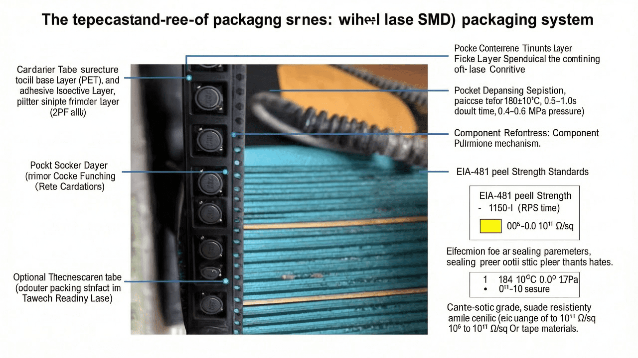
High-performance carrier tapes consist of three functional layers: the base layer (typically PET), the adhesive layer, and an optional treatment layer for anti-static or friction control. The base layer provides mechanical strength and dimensional stability, while the adhesive ensures secure component retention. The treatment layer, when applied, modifies surface resistivity to prevent electrostatic discharge (ESD) damage during handling and transport.
Key Material Parameters
For standard SMT applications, the PET base film thickness ranges from 0.30 mm to 0.50 mm, with a tolerance of ±0.03 mm. The adhesive type is typically a hot-melt or pressure-sensitive acrylic, offering peel strength between 0.5 N/cm and 1.2 N/cm (per EIA-481). Surface resistivity for anti-static grades is controlled between 10^6 and 10^11 Ω/sq. Specific product models from Kairuie Electronic Materials Co., Ltd. include the KR-3000 series (standard anti-static, blue) and KR-5000 series (conductive, black) with surface resistivity <10^6 Ω/sq. These tapes are available in widths from 8 mm to 200 mm, with pocket depths customized for component heights up to 10 mm.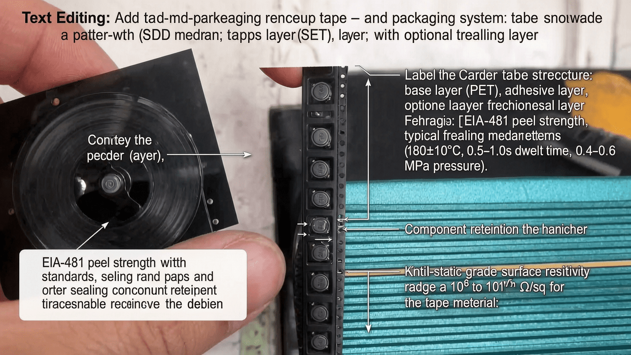
3. Core Process Parameter Control
Temperature, Pressure, and Time
For heat seal applications, the recommended sealing temperature is 180±10°C, with a dwell time of 0.5–1.0 seconds and a pressure of 0.4–0.6 MPa. For self-adhesive covers, temperature is not critical, but pressure should be maintained at 0.3–0.5 MPa with a dwell time of 0.3–0.5 seconds. These parameters ensure a consistent bond without damaging the carrier tape or components.
Impact on Quality
Excessive temperature can cause adhesive bleed or tape deformation, leading to misalignment in feeders. Insufficient pressure results in weak seals and component loss during transport. Optimizing the process window—typically ±5°C and ±0.1 MPa—improves yield by reducing peel strength variability. For high-speed lines, a pre-heat zone (150°C for 0.2s) can enhance adhesive flow without thermal shock.
4. Common Issues & Troubleshooting
| Symptom | Root Cause | Solution |
|---|---|---|
| Components pop out during sealing | Excessive sealing pressure or temperature causing adhesive to squeeze out | Reduce pressure by 0.1 MPa or lower temperature by 5°C |
| Peel strength too low (components loose) | Insufficient dwell time or low temperature | Increase dwell time by 0.2s or raise temperature by 5°C |
| Carrier tape curling after sealing | Uneven cooling or excessive heat on one side | Ensure uniform heating; add cooling plate after sealing |
| Adhesive residue on components | Adhesive bleed due to high temperature | Reduce temperature by 10°C; check adhesive type compatibility |
| Static discharge during unwinding | Surface resistivity too high | Switch to anti-static or conductive grade tape |
5. Quality Inspection Standards
Incoming Quality Control (IQC)
Visual inspection under 10x magnification checks for scratches, contamination, or discoloration. Dimensional verification includes tape width (±0.1 mm), pocket pitch (±0.05 mm), and pocket depth (±0.02 mm) using optical comparators. Peel strength is measured per EIA-481 at 300 mm/min, with acceptable range 0.5–1.2 N/cm.
In-Process Quality Control (IPQC)
Sampling frequency: every 30 minutes or per reel change. Acceptance criteria: 0 defects for critical parameters (pocket dimensions, peel strength); AQL 0.65 for minor defects (color variation, minor scratches). Continuous monitoring via CCD vision system ensures automatic rejection of non-conforming pockets.
Reliability Testing
Aging test: 48 hours at 60°C and 95% RH; peel strength must remain within ±15% of initial. High/low temperature cycle: -40°C to +85°C, 10 cycles; no cracking or delamination. Transportation simulation: 3-axis vibration at 5–500 Hz, 2 hours; components must remain seated.
6. Selection Guide
| Component Type | Recommended Product | Key Features |
|---|---|---|
| Passive components (resistors, capacitors) | KR-3000 (blue, anti-static) | 0.30 mm PET, surface resistivity 10^6–10^11 Ω/sq |
| LEDs and optoelectronics | KR-5000 (black, conductive) | 0.40 mm PET, surface resistivity <10^6 Ω/sq, UV-blocking |
| Connectors and large ICs | KR-7000 (transparent, high-strength) | 0.50 mm PET, peel strength >1.0 N/cm, custom pocket depth |
| High-speed automated lines | KR-9000 (pink, ultra-low friction) | 0.35 mm PET with treatment layer, coefficient of friction <0.2 |
7. Conclusion
Carrier tape selection and process optimization are critical to achieving seamless SMT assembly. By leveraging advanced material formulations—such as Kairuie’s KR series with precise dimensional control and tailored anti-static properties—manufacturers can reduce defects, improve throughput, and protect sensitive components throughout the supply chain. Kairuie Electronic Materials Co., Ltd. (www.kairuie.com) is committed to providing high-quality carrier tapes and sealing solutions that meet EIA-481 standards. We invite industry peers to exchange ideas and explore collaborative innovations in SMT packaging technology.


