凯瑞尔电子材料
1. Introduction
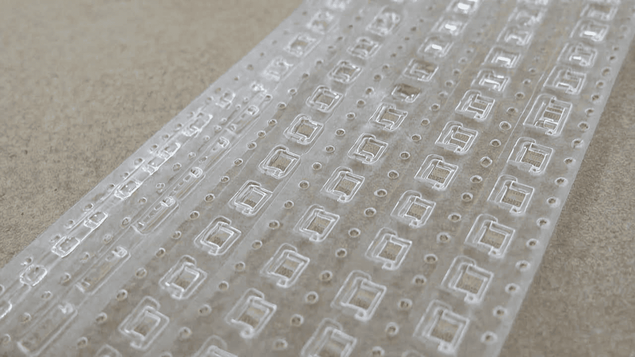
In the field of Surface Mount Technology (SMT), the reliability of tape-and-reel packaging directly determines the efficiency of automated assembly and the final quality of electronic products. As a high-performance carrier tape, the PP adhesive-backed carrier tape (PP点胶背模带) plays a critical role in the secure positioning and protection of components such as dispensing inductors (点胶电感) and SMT connectors. This article provides a comprehensive technical analysis of this product, covering its structure, material composition, process parameters, troubleshooting, quality standards, and selection guide, aiming to assist engineers and procurement professionals in optimizing their packaging solutions.
2. Product Structure & Material Composition
2.1 Layer Structure
The PP adhesive-backed carrier tape consists of three functional layers: a base layer (PP film), an adhesive layer (pressure-sensitive adhesive), and an optional anti-static treatment layer. The base layer provides mechanical strength and dimensional stability, while the adhesive layer ensures reliable bonding to the cover tape at room temperature without heat activation.
2.2 Key Material Parameters
The typical PET thickness of the carrier tape ranges from 0.3 mm to 0.5 mm, depending on component weight and size. The adhesive type is pressure-sensitive (PSA), which bonds under pressure at ambient temperature. Surface resistivity is controlled to achieve anti-static (10¹¹–10¹² Ω/sq) or static dissipative (10⁶–10¹¹ Ω/sq) performance, meeting ESD protection requirements. Each roll is 200 m long, compatible with PS and PP carrier tape materials.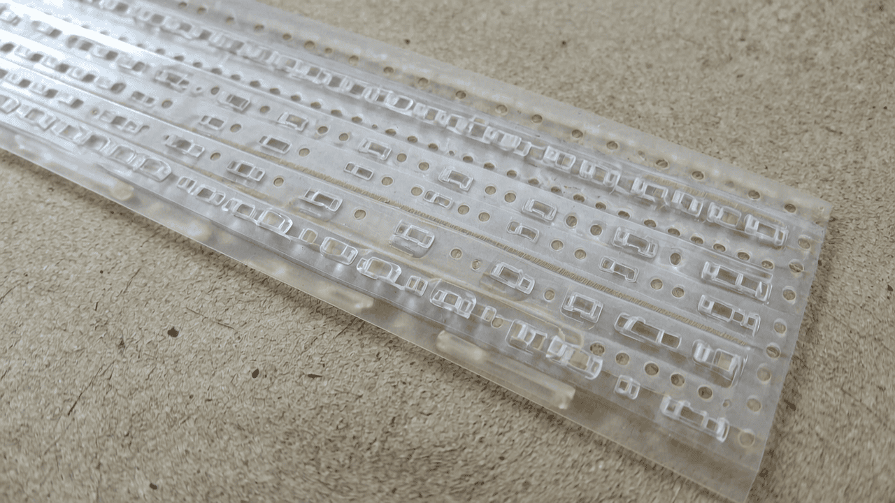
2.3 Reference Specifications
According to EIA-481 standard, the carrier tape widths range from 8 mm to 200 mm, and the product is suitable for embossed carrier tapes used in automated SMT assembly. The adhesive-backed design eliminates the need for heating, simplifying the sealing process and reducing energy consumption.
3. Core Process Parameter Control
3.1 Temperature, Pressure, and Time Recommendations
Since the cover tape is pressure-sensitive, no heating is required. The recommended lamination pressure is 2–5 kg/cm², applied for 0.5–1.0 seconds at ambient temperature (20–25°C). For high-speed machines, pressure may be adjusted to 3–4 kg/cm² to ensure consistent peel strength.
3.2 Effect of Parameters on Quality
Insufficient pressure leads to weak adhesion, causing cover tape lift-off during handling. Excessive pressure may deform the carrier tape pockets or damage components. Proper pressure ensures peel force within the 0.1–1.0 N range (per EIA-481).
3.3 Process Window Optimization
To achieve optimal peel strength, the adhesive layer must be fully activated by pressure. For high-humidity environments (>60% RH), pre-drying of the cover tape at 40°C for 30 minutes is recommended. A process window of 2.5–4.5 kg/cm² pressure and 0.5–1.0 s dwell time is typical.
4. Common Issues & Troubleshooting
| Symptom | Root Cause | Solution |
|---|---|---|
| Cover tape lifts from carrier tape | Insufficient lamination pressure | Increase pressure to 3.5 kg/cm² |
| Peel force too high (>1.0 N) | Excessive pressure or adhesive aging | Reduce pressure; replace cover tape |
| Component misalignment in pocket | Carrier tape pocket deformation | Reduce lamination pressure; check pocket dimensions |
| Static discharge damage | Inadequate anti-static property | Use static dissipative cover tape (<10¹¹ Ω/sq) |
| Cover tape wrinkles | Uneven pressure or tape misalignment | Adjust pressure roller alignment; ensure tape flatness |
5. Quality Inspection Standards
5.1 Incoming Quality Control (IQC)
Visual inspection for scratches, contamination, and color uniformity. Dimensional check of tape width (±0.1 mm) and pocket pitch (±0.05 mm). Peel strength test per EIA-481: 0.1–1.0 N at 300 mm/min peel speed.
5.2 In-Process Quality Control (IPQC)
Sampling frequency: every 30 minutes or per reel change. Acceptance criteria: peel force within 0.2–0.8 N, no cover tape lift, no component shift. Visual inspection under 10x magnification.
5.3 Reliability Testing
Aging test: 85°C/85% RH for 168 hours, then peel force re-measurement (must remain within spec). High/low temperature cycling: -40°C to +85°C, 10 cycles, no delamination. Transportation simulation: vibration (10–500 Hz, 1.5 g) and drop test (1 m height) with no component loss.
6. Selection Guide
| Component Type | Recommended Product | Key Parameters |
|---|---|---|
| Dispensing Inductor (点胶电感) | PP点胶背模带, Anti-static grade | Tape width: 12–24 mm; Peel force: 0.3–0.6 N; Surface resistivity: 10¹¹–10¹² Ω/sq |
| SMT Connector | PP点胶背模带, Static dissipative grade | Tape width: 16–32 mm; Peel force: 0.5–0.8 N; Surface resistivity: 10⁶–10¹¹ Ω/sq |
| LED / Resistor / Capacitor | PP点胶背模带, Universal type | Tape width: 8–12 mm; Peel force: 0.1–0.4 N; Standard anti-static |
| Large IC / BGA | PP点胶背模带, Conductive grade | Tape width: 32–200 mm; Peel force: 0.6–1.0 N; Surface resistivity: <10⁶ Ω/sq |
7. Conclusion
The PP adhesive-backed carrier tape (PP点胶背模带) offers a reliable, cost-effective, and ESD-safe packaging solution for a wide range of SMT components, including dispensing inductors and connectors. Its pressure-sensitive adhesive eliminates the need for heating, simplifying the sealing process while maintaining consistent peel performance. Kairuie Electronic Materials Co., Ltd. is committed to providing high-quality carrier tapes that meet EIA-481 standards and customer-specific requirements. For more information, visit our website at www.kairuie.com. We welcome industry peers to exchange ideas and explore innovative packaging solutions together.


