凯瑞尔电子材料
1. Introduction
In the high-precision world of surface-mount technology (SMT), electronic component packaging plays a pivotal role in ensuring the integrity, reliability, and efficiency of automated assembly lines. The carrier tape, together with its cover tape and reel, forms the primary protection and transportation medium for semiconductor chips, resistors, capacitors, connectors, and other sensitive devices. As electronic components continue to shrink in size and increase in complexity, the demand for packaging solutions that offer not only mechanical protection but also stringent electrostatic discharge (ESD) control and cleanliness has become paramount. Kairuie Electronic Materials Co., Ltd. has been at the forefront of developing advanced carrier tape systems that address these exacting requirements. This article delves into the critical aspects of anti-static carrier tape design specifically tailored for semiconductor cleanroom environments. We will explore the material composition, structural features, process parameter control, common troubleshooting techniques, quality inspection standards, and a practical selection guide to help engineers and procurement professionals make informed decisions.
2. Product Structure & Material Composition
2.1 Carrier Tape Material Options
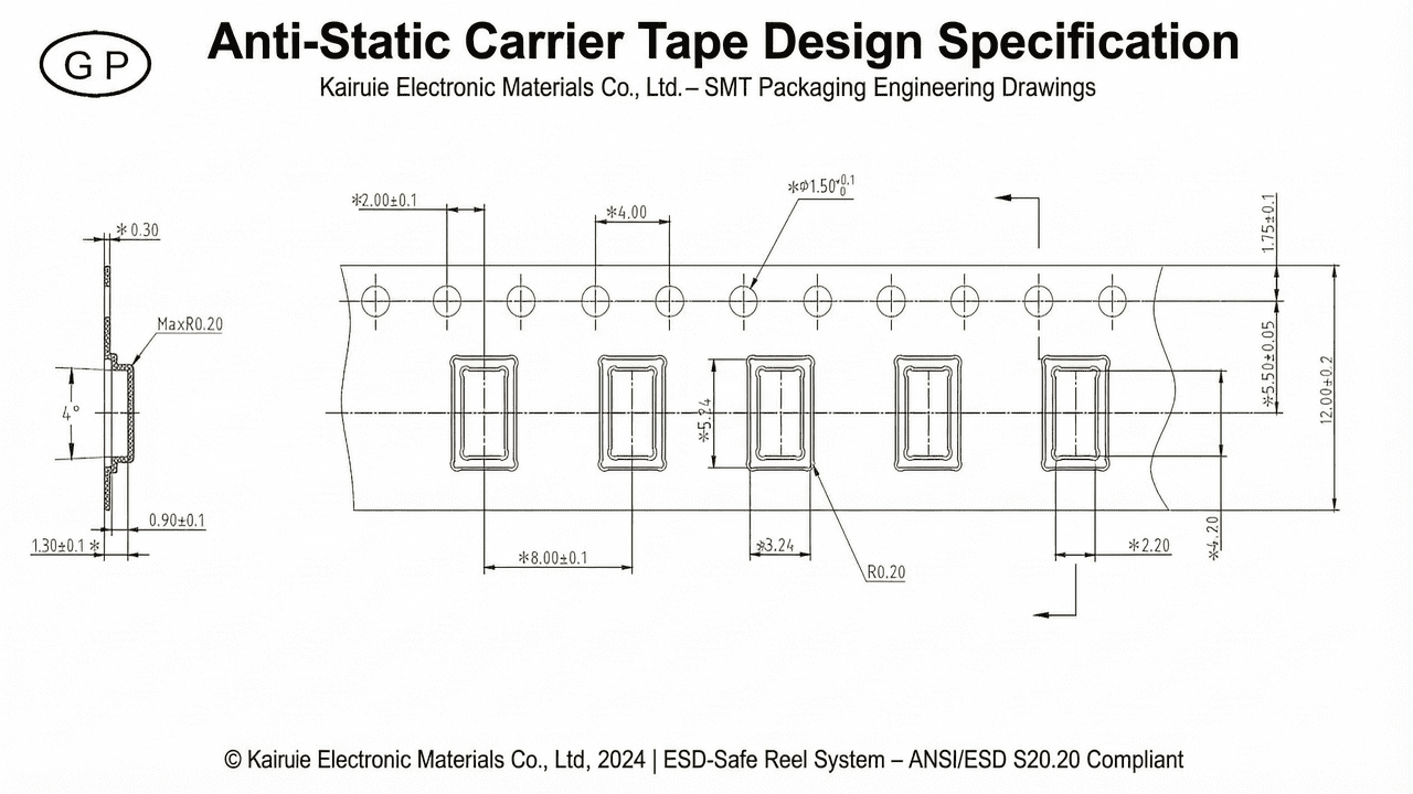
The carrier tape is typically an embossed or punched plastic strip with precision-formed pockets that hold individual components. The choice of material directly influences the tape’s mechanical strength, thermal stability, optical clarity, and ESD properties. Kairuie offers several base material options, each suited to different application scenarios. Polystyrene (PS) is the most cost-effective choice for general-purpose SMT components, available in transparent or black grades. For applications requiring visual inspection of pocket contents, transparent PS allows clear optical verification. Polycarbonate (PC) provides superior temperature resistance, withstanding baking processes up to 125°C, making it ideal for moisture-sensitive devices. Polyethylene terephthalate (PET) extends thermal capability to 150°C and offers excellent dimensional stability. For flexible, bend-resistant packaging, especially for hardware parts, polypropylene (PP) is recommended. Each material can be engineered with anti-static additives or coatings to achieve surface resistivity between 104 and 1011 ohms/sq, per ANSI/ESD S20.20 standards. Critical parameters include pocket dimensional accuracy (±0.05 mm), camber control (<1 mm over 500 mm), and consistent pitch distance (±0.1 mm) to ensure seamless feeding in high-speed SMT placement machines.
2.2 Anti-Static Coating and Surface Resistivity
Electrostatic discharge is a leading cause of latent component failures in semiconductor handling. Kairuie’s anti-static carrier tapes incorporate either a dissipative coating or a co-extruded layer that provides a permanent, humidity-independent static dissipative property. The surface resistivity is carefully controlled within the dissipative range (104 to 1011 ohms/sq) to prevent rapid charge generation and enable safe discharge. For standard ESD protection, PS antistatic (black or transparent) is widely used. For components requiring higher temperature processing, PC antistatic and PET antistatic grades maintain their electrical properties even after thermal aging. The antistatic treatment is designed to be non-contaminating, with no measurable outgassing or particulate shedding, meeting ISO 14644-1 Class 5 cleanroom compatibility. Sampling resistivity is verified using concentric ring probe methods per IEC 61340-2-3, and the typical lot-to-lot variation is kept within ±0.5 order of magnitude. The material also features low static decay time (<0.05 s) from 1000 V to 100 V, ensuring rapid charge dissipation during processing.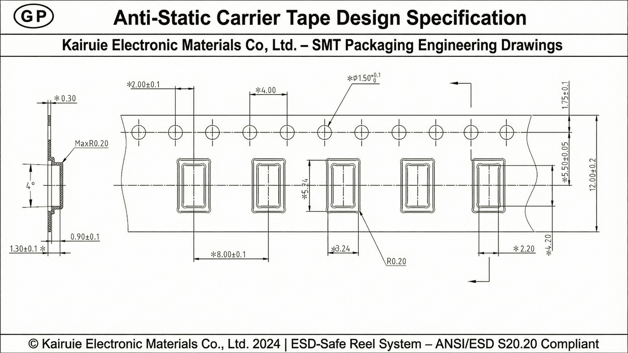
2.3 Cover Tape and Reel Compatibility
A complete tape-and-reel system comprises the carrier tape, the heat-activated or pressure-sensitive cover tape, and the plastic reel. The cover tape must provide consistent peel strength (typically 30–90 gf for 8 mm wide tapes) while maintaining a hermetic seal to protect components from moisture and particulates. Kairuie’s heat-activated adhesive (HAA) cover tapes are formulated to bond securely with the carrier tape’s top surface, offering a balanced adhesion that prevents premature peel-off during reeling or transportation, yet releases smoothly at the SMT feeder. The peel strength is tested per EIA-481-D at an angle of 165–180° and a speed of 300 mm/min. The reel is available in two configurations: the split-type reel for flexible width changes in low-volume production, and the one-piece reel for high-speed automated lines requiring maximum stability. Anti-static reels (surface resistivity 106–109 ohms) are recommended for ICs and MOSFETs, while standard reels suffice for passive components.
3. Core Process Parameter Control
3.1 Sealing Temperature Profile
For heat-activated cover tape sealing, precise temperature control is critical to achieve optimal bond strength without deforming the carrier tape or damaging components. Kairuie recommends a sealing temperature range of 140–180°C for PS-based tapes, 160–200°C for PC, and 180–210°C for PET, depending on the cover tape adhesive chemistry and line speed. The actual temperature at the sealing shoe should be verified with a calibrated thermocouple to ensure uniformity across the width. A typical tolerance of ±5°C is maintained. For antistatic grades, excessive temperature can degrade the surface resistivity; thus, process validation must include post-seal resistivity checks per IPC/JEDEC J-STD-033. Thermal profiling of the sealing zone is conducted weekly to detect any drift.
3.2 Pressure and Dwell Time
The sealing pressure, usually applied via spring-loaded or pneumatic shoe mechanisms, should be set between 200–400 gf/cm of tape width for consistent bond line formation. Dwell time, the interval the tape remains under the heated shoe, is typically 0.2–0.6 seconds per index. At higher line speeds (up to 120 pockets/min), dwell time may be at the lower end, requiring precise synchronisation of the sealer’s cam or servo drive. Insufficient pressure or time leads to weak peel strength and potential cover tape lift, while excessive values may cause adhesive squeeze-out or carrier tape warping. A Design of Experiments (DOE) is employed during new product introduction to map the process window, with peel strength as the primary response variable.
3.3 Process Window Optimization
The interaction between temperature, pressure, and speed defines a three-dimensional process window. Kairuie’s technical team performs comprehensive DOE studies to identify the robust center point. For instance, a typical robust window for PS antistatic tape with HAA cover tape is: temperature 160°C ±10°C, pressure 300 gf/cm ±50 gf/cm, dwell time 0.4 s ±0.1 s. This window ensures a peel strength of 50–70 gf, well within the EIA-481-D spec of 30–100 gf. Statistical process control (SPC) charts for peel strength are maintained, with Cp and Cpk values exceeding 1.33. Additionally, moisture barrier performance is verified by exposing sealed packages to 85°C/85% RH for 168 hours, confirming no delamination or weight gain beyond the specified Moisture Sensitivity Level.
4. Common Issues & Troubleshooting
4.1 Typical Defects and Solutions
Even with robust processes, occasional defects may arise. The following table summarizes five common issues encountered with anti-static carrier tape packaging, their root causes, and recommended corrective actions.
| Symptom | Root Cause | Solution |
|---|---|---|
| Peel strength too low (cover tape lifts during transport) | Insufficient sealing temperature, pressure, or dwell time; contaminated sealing surface | Increase temperature by 5°C increments until target peel strength achieved; clean sealing shoe; verify pressure gauge calibration |
| Peel strength too high (tape tearing or component damage) | Excessive temperature or dwell time; cover tape adhesive too aggressive for carrier material | Reduce temperature; decrease dwell time; switch to lower-adhesion cover tape formulation; verify use of proper material combination |
| Component sticking to cover tape adhesive | Cover tape adhesive protruding into pocket; static charge causing component adhesion | Adjust sealing shoe alignment to center the cover tape over sprocket holes; check for adhesive squeeze-out; verify antistatic performance of both carrier and cover tapes |
| Camber (tape curvature) causing feeding errors | Improper reeling tension; uneven thickness distribution; material relaxation | Reduce reel winding tension; store reels horizontally to prevent sag; inspect incoming material for camber <1 mm; use stiffer material grade (e.g., PC instead of PS) |
| Electrostatic discharge damage to components | Surface resistivity out of spec; antistatic layer worn off during sealing; improper grounding of equipment | Measure resistivity of each lot; replace worn sealing shoes; ensure all equipment properly grounded; use ionization bars in critical zones |
Regularly monitoring these symptoms through process audits and statistical analysis minimizes downtime and scrap.
5. Quality Inspection Standards
5.1 Incoming Quality Control (IQC)
Upon receipt, all raw materials undergo rigorous IQC to ensure they meet specifications. Visual inspection checks for surface defects, discoloration, and clear sprocket holes. Dimensional verification using a precision vision system measures pocket width, length, depth (typically to ±0.05 mm for fine-pitch pockets), pitch distance (e.g., 4 mm, 8 mm), and overall tape width. Peel strength testing is performed on a sample basis using a tensile tester at the specified peel angle and speed. Surface resistivity is measured per IEC 61340-2-3, with acceptance criteria between 104 and 1011 ohms/sq. Additionally, the moisture content of paper-based punched carriers is verified to be below 1.5% to prevent pocket collapse during baking. All test results are documented in the lot inspection report, and only materials meeting all criteria are released to production.
5.2 In-Process Quality Control (IPQC)
During the tape forming and sealing process, IPQC sampling is conducted every 500 meters of tape or every production shift, whichever comes first. A sample of at least 5 consecutive pockets is inspected for dimensional conformance and visual defects. Peel strength is tested at three points along the tape width (left, center, right) to ensure sealing uniformity. For antistatic tapes, surface resistivity is checked every two hours at the production line to detect any degradation from high sealing temperatures. Statistical process control charts track key parameters like seal strength (target ± 3σ limits). If any measurement falls outside the control limits, production is halted, and the previous 500 meters are quarantined for 100% inspection. Real-time camber monitoring using laser sensors is implemented on high-speed lines to immediately flag out-of-spec curvature.
5.3 Reliability Testing
To guarantee long-term performance, finished tape-and-reel packages undergo a battery of reliability tests. These include a 168-hour aging test at 85°C/85% RH to assess moisture resistance and adhesive stability. Thermal cycling from -40°C to +85°C (100 cycles) simulates transportation and storage extremes. Transport simulation per ISTA 3A subjects packaged reels to vibration and drop tests to ensure cover tape integrity and component retention. Post-test peel strength must remain within the original acceptance range, and no components should be loose or misoriented. Surface resistivity is re-measured after aging to confirm the permanence of the antistatic properties. Kairuie’s products consistently pass these tests, with peel strength variation less than 15% from initial values, confirming reliability under harsh conditions.
6. Selection Guide
6.1 Recommended Solutions by Component Type
Selecting the optimal carrier tape material depends on the specific component requirements. The following table provides a quick reference based on common semiconductor and electronic component types.
| Component Type | Recommended Material | Key Reason |
|---|---|---|
| Standard passive components (0402, 0603) | PS Transparent (Non-Antistatic) | Cost-effective, sufficient mechanical protection |
| ICs, microcontrollers, MOSFETs | PS Antistatic / PC Antistatic | ESD protection required; PC if baking >125°C |
| High-temperature devices (e.g., power modules, SiC) | PET Transparent Antistatic | Withstands 150°C baking, antistatic available |
| Connectors, sockets, precision hardware | PP Transparent | Flexible, bend-resistant, good for bulky parts |
| LEDs, optical sensors | PC Transparent | Optical clarity for visual inspection; anti-static optional |
Kairuie offers all these materials in various pocket dimensions and pitch configurations, tailored to exact component outlines.
6.2 Reel Type Selection
The choice of reel design impacts both production efficiency and component safety. The table below compares the two main reel types offered by Kairuie.
| Customer Requirement | Recommended Reel Type | Comments |
|---|---|---|
| Multiple product types, small batches, flexible width changes | Split-Type Reel | Adjustable flanges allow quick width change; cost-effective for low volumes |
| High-volume, high-speed automated lines | One-Piece Reel | Rigid structure minimizes wobble at high unwinding speeds; best for stability |
| Packaging standard resistors and capacitors | Non-Anti-Static Reel | No ESD concern; lower cost |
| Packaging sensitive ICs, MOSFETs | Anti-Static (Dissipative) Reel | Surface resistivity 106–109 ohms; ensures ESD safety |
| Visual inspection of components required | Transparent Reel | Clear polystyrene or polycarbonate options |
Custom colour and branding options are available upon request.
7. Conclusion
Kairuie Electronic Materials Co., Ltd. delivers a comprehensive portfolio of anti-static carrier tape, cover tape, and reel solutions engineered for the demanding environments of semiconductor and SMT assembly. By combining advanced material science, precision manufacturing, and rigorous quality management, we ensure that each component is securely packaged, protected from ESD, and maintained in a cleanroom-compatible state from tape-and-reel forming to the SMT placement machine. Our products, available in PS, PC, PET, and PP with tailored anti-static properties, meet international standards such as ANSI/ESD S20.20 and EIA-481-D, providing reliable performance across a wide range of component types and process conditions. We invite industry peers to explore our solutions and exchange technical insights. For more information, please visit our website at www.kairuie.com or contact our technical support team. Together, we can advance the reliability and efficiency of electronic packaging.


