凯瑞尔电子材料
1. Introduction
The Critical Role of Carrier Tape Dimensional Accuracy in SMT Packaging
In surface mount technology (SMT), the carrier tape is far more than a simple packaging medium—it is the critical interface between component manufacturing and high-speed automated assembly. Every second, pick-and-place machines rely on the precise geometry of carrier tape pockets, sprocket holes, and overall dimensions to reliably extract and position minuscule electronic components. A deviation of just a few hundredths of a millimeter in pocket width, pitch, or depth can cause missed picks, component damage, or feeder jams, leading to costly downtime and reduced first-pass yield. As electronic devices shrink and component tolerances tighten to 0201 or even 01005 sizes, the demand for zero-defect carrier tape has never been higher. Kairuie Electronic Materials Co., Ltd. addresses this challenge with an advanced taping machine equipped with a full-dimensional CCD measurement system, capable of inspecting every critical dimension on every single pocket. This article provides a comprehensive technical exploration of this solution, covering its structure, process parameters, common issues, quality inspection standards, and selection guidelines, to demonstrate how precision metrology integrated into the packaging process ensures flawless SMT pick-and-place performance.
2. Product Structure and Key Components
Machine Architecture and Key Components
The Kairuie Taping Machine is engineered as a modular, high-precision system that seamlessly combines manual component placement, automated CCD vision inspection, automatic reject removal, and sealing/rewinding into one compact footprint. Its core architecture includes a precision-indexed tape transport mechanism that advances the carrier tape through each station with a positional accuracy of ±0.02 mm. At the loading station, operators or automated feeders place components into the formed pockets. The tape then passes under a high-resolution CCD camera array, where every pocket is imaged and measured. An integrated reject station, triggered in real time by the inspection system, removes any pocket containing an out-of-tolerance component or dimensional defect. Finally, the tape is sealed—either by heat or pressure-sensitive adhesive—and rewound onto a reel ready for shipment. The machine supports a carrier tape width range from 8 mm to 56 mm as standard, with custom engineering extending capability to 88 mm. The dual-mode sealing system is a standout feature: heat-seal for standard cover tapes and self-adhesive for pressure-sensitive adhesive cover tapes, switchable via the human-machine interface (HMI) without mechanical changeover. This design philosophy emphasizes flexibility and reliability, ensuring that the machine can adapt to diverse production environments and component types.
CCD Vision System Specifications
At the heart of the machine lies the full-dimensional CCD measurement system. It employs multiple high-speed digital cameras with telecentric lenses that eliminate perspective distortion, combined with advanced LED ring lighting to achieve crisp, high-contrast images regardless of carrier tape surface reflectance. The system measures all critical dimensions as defined in global packaging standards: W (carrier tape width), E (sprocket hole pitch), P0 (individual pocket pitch), P2 (center distance between adjacent pockets), F (sprocket hole to pocket edge), D0 (sprocket hole diameter), D1 (top hole diameter), A0 (pocket length), B0 (pocket width), and K0 (pocket depth). Each parameter is inspected with a repeatable accuracy of ±0.05 mm, while cumulative pitch error over 10 consecutive pockets is held to ±0.05 mm. These tolerances are verified through a built-in calibration routine using a certified glass scale. Images are analyzed using proprietary edge-detection algorithms that can identify burrs, flash, or deformation in pocket geometry. The cycle time for full inspection of one pocket is less than 50 milliseconds, enabling line speeds up to 12,000 pockets per hour. Out-of-tolerance pockets are automatically marked and ejected before sealing, ensuring that only conforming product reaches the customer. The software also supports pattern recognition for different pocket shapes and sizes, making it suitable for components ranging from 0201 passives to large connectors.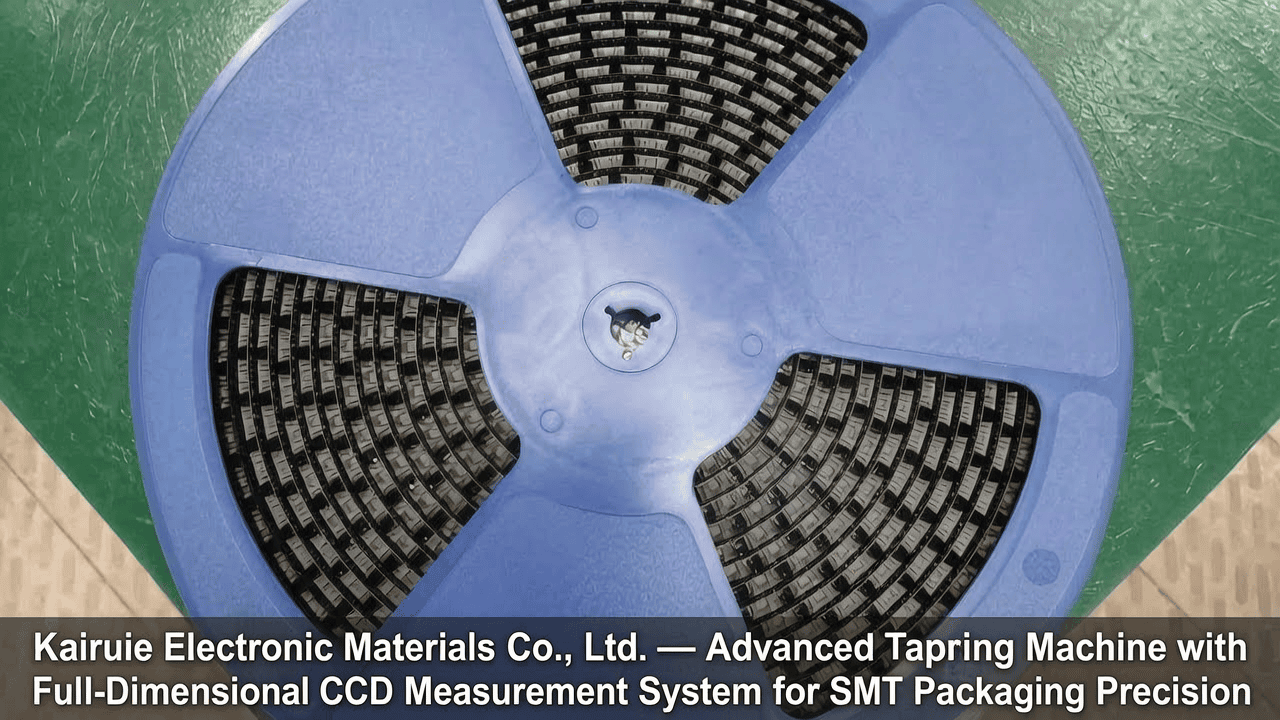
Supported Carrier Tape Formats and Material Compatibility
The CCD measurement system is designed to accommodate a wide spectrum of carrier tape materials, including conductive and non-conductive polystyrene, polycarbonate, and PET. It handles standard tape widths from 8 mm up to 88 mm and pocket depths from 0.5 mm to over 10 mm, covering virtually all SMT components. The machine’s recipe management system stores over 100 unique tape profiles, each containing the nominal dimensions and tolerance limits for a specific product. When changing over to a new tape format, the operator simply loads the corresponding recipe, and the system adjusts camera positions, lighting intensity, and inspection parameters automatically. For cover tapes, the dual-mode sealing capability means the same machine can process both heat-activated and pressure-sensitive adhesives. Heat sealing parameters such as temperature (160–200°C), pressure (0.3–0.5 MPa), and dwell time (0.5–2.0 seconds) are precisely controlled through closed-loop feedback, while the self-adhesive mode uses a contoured roller system to apply uniform pressure without heat. This material flexibility is crucial for packaging moisture-sensitive devices that require a hermetic heat seal or components that benefit from the lower stress of pressure-sensitive sealing.
3. Core Process Parameter Control
Sealing Process Parameter Optimization
Achieving a robust, peelable seal is a delicate balance of temperature, pressure, and time. For heat-seal cover tapes, the recommended temperature range is 160–200°C, depending on the adhesive activation threshold and substrate material. Excessively low temperatures result in weak seals that can open during transport, while excessive heat can transfer to the component, causing thermal damage or warping of the carrier tape. The machine’s sealing head incorporates multiple thermocouples and a PID controller that maintains temperature uniformity within ±1°C across the 150 mm sealing zone. Pressure, typically set between 0.3–0.5 MPa, must be sufficient to penetrate the adhesive into the carrier tape surface texture without crushing the component. Dwell time ranges from 0.5 to 2 seconds and directly influences the seal’s peel strength, which should ideally fall between 30–80 grams for 8 mm tape, as per IPC/JEDEC J-STD-033. The system allows independent adjustment of each parameter via the HMI, and the data are logged for traceability. For self-adhesive cover tape, the process is pressure-only; a spring-loaded roller applies a calibrated force to press the tape onto the carrier, ensuring a consistent bond line. Process capability studies have demonstrated a Cpk greater than 1.67 for peel strength when these parameters are tightly controlled. Regular cleaning and maintenance of the sealing head prevent adhesive buildup, which can lead to inconsistent sealing.
CCD Inspection Process Settings
Optimizing CCD inspection parameters is essential to achieve high throughput while maintaining zero escape of dimensional defects. The primary settings include exposure time, gain, and region-of-interest (ROI) definition. The system’s auto-calibration function uses a master tape that has been certified with a coordinate measurement machine (CMM) to set initial thresholds. In production, each dimension’s pass/fail limit is typically set at 80% of the specification tolerance to provide a guard band against measurement uncertainty and process drift. For example, with a tolerance of ±0.05 mm, the internal reject limit may be ±0.04 mm. Lighting is adjusted per tape color and transparency; dark conductive tapes require higher intensity to avoid edge blooming, while clear PET tapes need polarization filters to reduce glare. Inspection speed is inversely related to the number of measurements taken; a balance is achieved by sequencing critical dimensions first and aborting further measurements if a pocket fails early. The machine software employs statistical process control (SPC) charts that trend dimensional data in real time, alerting operators to shifts in tape forming or guide rail alignment before defects become severe. A recipe lock-out feature prevents unauthorized changes, and all inspection results are stored in a database for quality audit trails. This systematic control ensures that all shipped carrier tape meets the stringent ±0.05 mm standard.
4. Common Issues and Troubleshooting
Typical Problems and Solutions
| Symptom | Root Cause | Solution |
|---|---|---|
| CCD detects repeated pocket dimension out-of-tolerance | Misaligned tape guide or worn pocket forming dies | Recalibrate tape guide alignment; replace worn pocket forming dies per preventative maintenance schedule |
| Intermittent false rejects from CCD | Dust on camera lens or inconsistent lighting | Clean lens and lighting elements with approved optic cleaner; adjust inspection sensitivity and verify uniformity with test tape |
| Poor seal strength leading to cover tape peeling | Insufficient sealing temperature/pressure | Increase temperature within recommended range (160-200°C) by 5°C increments; verify pressure uniformity using pressure-indicating film |
| Carrier tape jamming during feeding | Incorrect sprocket hole pitch or tape width variation | Check tape incoming quality with gauge; adjust tension; clean and realign feed mechanism; replace worn sprocket rollers |
| Seal deformation or component damage | Excessive sealing temperature or dwell time | Reduce temperature or dwell time; ensure components are fully seated in pockets; verify cover tape does not protrude excessively |
In addition to these measures, the Kairuie machine provides real-time diagnostics through the HMI, which logs errors and suggests corrective actions. Routine maintenance, including daily cleaning of the CCD optical path and monthly verification of calibration, can prevent many of these issues. When persistent problems occur, Kairuie’s service team offers remote support and on-site assistance to minimize downtime.
5. Quality Inspection Standards
Incoming Quality Control (IQC)
Before carrier tape or cover tape materials enter the production line, rigorous IQC procedures are enforced to prevent defective raw materials from affecting the final product. Incoming carrier tape reels undergo visual inspection under 10x magnification for surface defects, contamination, or inconsistent pocket formation. Critical dimensions—W, E, P0, A0, B0, and K0—are measured on a sample of 10 pockets using a calibrated vision measuring machine, and results must conform to the supplier’s specification or the ±0.05 mm Kairuie standard, whichever is tighter. Peel strength of the cover tape adhesive is tested on a tensile tester per IPC-TM-650; values must be within the agreed specification (typically 30–80 g for 8 mm tape). Any lot that fails is quarantined and returned. Additionally, the CCD inspection system itself is used for first-article inspection of each new tape batch: a full reel is loaded, and all pockets are inspected to verify that the forming process is stable. Acceptance criteria require zero critical defects and a dimensional Cpk above 1.33. Documentation of IQC results is maintained for traceability and serves as a baseline for process control.
In-Process Quality Control (IPQC)
During the taping operation, IPQC ensures that every component package meets the highest standards. The machine performs 100% CCD inspection on every pocket, with automatic rejection of any pocket that fails dimensional or presence checks. Destructive peel tests are conducted on sealed samples at a frequency of one test per 1000 pockets, or as defined by the control plan, to verify seal integrity. Peel strength is recorded and plotted on an SPC chart; any downward trend triggers an alert to adjust sealing parameters. Additionally, the operator periodically checks the alignment of the cover tape and carrier tape edges using a go/no-go gauge to ensure no wrap-around or overhang exceeds 0.2 mm. The inspection data are compiled into a batch report that includes Cp and Cpk indices for all measured dimensions. Acceptance criteria: no dimension may exceed the specification limit, and the cumulative defect rate must be zero for any critical defect category. The automatic reject removal system is verified every shift by intentionally introducing known bad pockets to confirm proper ejection. This layered approach guarantees that only fully conforming packaging leaves the machine.
Reliability Testing
To simulate the stresses of storage, transportation, and assembly, finished tape-and-reel packages undergo reliability testing. An aging test exposes sealed reels to 40°C and 95% relative humidity for 168 hours, after which peel strength and dimensional stability are rechecked. The seal must not degrade more than 15% from initial values. High/low temperature cycling from -40°C to +85°C for 100 cycles (soak time 15 minutes, ramp rate 10°C/min) verifies that the carrier tape and seal remain intact without cracking or delamination. Transportation simulation according to ISTA 2A includes random vibration for 60 minutes and a drop test from 76 cm, after which the package must show no seal breaches or component fallout. These tests confirm that Kairuie’s packaging maintains its integrity throughout the global supply chain, protecting components until they are presented to the pick-and-place nozzle.
6. Selection Guide
Recommended Configurations by Application
| Component Type | Recommended Configuration | Key Features |
|---|---|---|
| Passive chip components (0201-1206) | Standard CCD, heat seal, 8-12 mm tape | High-speed inspection, tight pocket dimensions, reliable sealing for high-volume |
| Small outline ICs (SOIC, TSSOP) | CCD with enhanced accuracy, dual-mode seal, 12-24 mm tape | Larger pocket measurement, self-adhesive option for moisture-sensitive parts |
| Connectors and odd-shaped parts | Custom CCD with multi-angle vision, vibratory bowl feeder, 24-56 mm tape | Flexibility for unique geometries, automatic reject, pneumatic sealing |
| High-reliability automotive parts | High-precision CCD, full traceability, dual-mode seal, wide tape up to 88 mm | Strictest dimensional tolerances, data logging, robust packaging for harsh environments |
Kairuie offers deep customization to match specific production requirements. Feeding methods can be configured as vibratory bowl, tray, tube, or bulk feeder. Marking/printing options include inkjet or laser for part identification. The inspection system can be upgraded to include 3D pocket depth measurement or component coplanarity checks. Our application engineers work with customers to define the optimal configuration, ensuring that the machine delivers the required throughput and zero-defect output. Contact us for a feasibility study on your unique component packaging challenge.
7. Conclusion
Ensuring Zero-Defect SMT Packaging with Advanced CCD Measurement
The Kairuie full-dimensional CCD carrier tape measurement system represents a quantum leap in quality assurance for electronic component packaging. By integrating high-speed, high-precision vision inspection with robust process control, it eliminates the dimensional variability that leads to pick-and-place failures. Every pocket is verified to ±0.05 mm, and only conforming packages are sealed and delivered. The flexibility to handle tape widths from 8 mm to 88 mm, dual-mode sealing, and customizable feeding and inspection options make it the ideal solution for a diverse range of components, from micro passives to large automotive modules. Kairuie Electronic Materials Co., Ltd. stands as a leader in electronic packaging innovation, committed to providing the industry with tools that enhance productivity and reliability. We invite you to visit us at www.kairuie.com to explore our full portfolio, request a demonstration, or discuss how we can collaborate to advance your SMT packaging process. Together, we can drive the future of electronics manufacturing toward ever greater precision and efficiency.


