凯瑞尔电子材料
1. Introduction
In modern surface mount technology (SMT) production, high-speed placement machines operate at rates exceeding 100,000 components per hour. Even minor deviations in carrier tape dimensions can cascade into costly disruptions: mis-picks, tape jamming, feeder errors, and excessive component waste. The root cause often lies in dimensional tolerances—particularly when pocket dimensions, feed hole pitch, or cover tape adhesion fall outside the tight windows demanded by precision placers. Kairuie Electronic Materials Co., Ltd. has developed a comprehensive line of high-precision carrier tapes that directly address these challenges. This article explores how advanced material engineering, strict process control, and tailored product design can eliminate the chronic issues of mis-pick and tape jamming, ensuring uninterrupted high-speed SMT assembly.
2. Product Structure & Material Composition
2.1 Multi-Layer Architecture
Kairuie’s high-precision carrier tapes are based on a multi-layer composite structure optimized for dimensional stability, antistatic performance, and reliable peel force. The primary layers include:
- Base film: Core material of biaxially oriented polyethylene terephthalate (BOPET) or impact-modified polystyrene (HIPS) , selected for consistent thermoforming and minimal shrinkage. For ultra-high precision, Kairuie offers enhanced PET with a thickness tolerance of ±5%.
- Antistatic coating: A permanent, humidity-independent conductive layer (typically PEDOT:PSS or sputtered ITO) provides surface resistivity of 10^8–10^11 Ω/sq, preventing electrostatic discharge (ESD) damage and dust attraction during high-speed unwinding.
- Adhesive system: For cover tape attachment, a heat-activated or pressure-sensitive adhesive (PSA) is selectively applied to the carrier tape’s rails. The adhesive is formulated to maintain a stable peel force (30–60 gf for standard, 15–40 gf for low-force applications) across a wide temperature and humidity range.
- Release liner (optional): A silicone-coated PET liner protects the adhesive prior to lamination, ensuring contamination-free bonding.
2.2 Key Technical Parameters
Precision begins with tight control over critical dimensions. Below are representative specifications for the Kairuie KR-E series, designed for 0402 to 0805 passives and small ICs: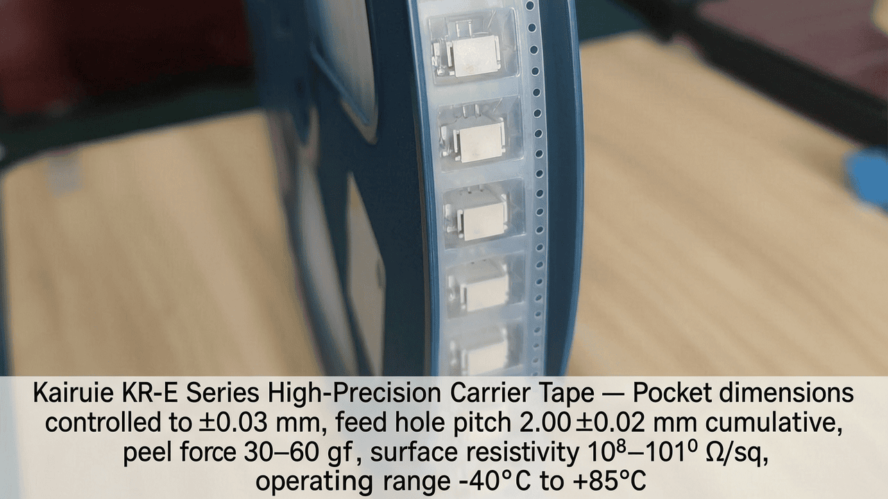
| Parameter | Standard Value | High-Precision Option |
|---|---|---|
| Base Material Thickness | 0.30 ±0.015 mm | 0.30 ±0.010 mm |
| Pocket Depth | 0.85 ±0.05 mm | 0.85 ±0.03 mm |
| Pocket Width (Ao) | 1.10 ±0.05 mm | 1.10 ±0.03 mm |
| Pocket Length (Bo) | 1.90 ±0.05 mm | 1.90 ±0.03 mm |
| Feed Hole Pitch (Po) | 2.00 ±0.03 mm (cumulative) | 2.00 ±0.02 mm (cumulative) |
| Surface Resistivity | 109–1011 Ω/sq | 108–1010 Ω/sq |
| Peel Force (to cover tape) | 40 ±10 gf | Customizable 20–60 gf |
| Operating Temperature | -10°C to +60°C | -40°C to +85°C |
These tight tolerances are achieved through precision tooling, in-line laser measurement, and statistical process control (SPC).
3. Core Process Parameter Control
3.1 Thermoforming Parameters
The pocket geometry is formed via a precisely controlled thermoforming process. Key parameters include:
- Temperature: Heating zone set to 180–220°C for PET (PS: 140–160°C). Uniform heating is critical—variations of ±3°C can alter pocket dimensions by up to 0.04 mm and affect crystallinity, leading to inconsistent peel force. Kairuie employs multi-zone IR heaters with closed-loop feedback and real-time temperature monitoring.
- Forming pressure: 3–5 bar (pneumatic) or 15–25 bar (hydraulic) depending on material. Pressure must be evenly distributed to ensure consistent pocket wall thickness. Our tools incorporate micro-vented plugs to eliminate trapped air, preventing thin spots that cause component tilting.
- Dwell time: 0.8–1.5 seconds. Excessive dwell time can over-form the pocket, increasing Ao/Bo; too short results in under-formed pockets with insufficient depth.
- Cooling: Post-forming rapid cooling to <40°C stabilizes dimensions and minimizes post-mold shrinkage. Kairuie’s in-line cooling stations reduce cycle time while locking in geometry.
3.2 Lamination Process
Applying cover tape with consistent peel force demands precise control:
- Nip pressure: 2–4 kg/cm, depending on adhesive type. Uneven pressure causes wavy peel curves and potential cover tape blow-off. Our lamination units use dual servo-driven rollers with force feedback.
- Temperature: For heat-activated adhesives, nip temperature is maintained at 150–180°C with a tolerance of ±5°C. Overheating can degrade the adhesive, while underheating reduces bond strength.
- Alignment: Cover tape edge-to-carrier alignment within ±0.1 mm to ensure straight peeling. Kairuie’s automatic tracking system ensures continuous correction.
3.3 Process Window Optimization
Design of experiments (DOE) has identified the optimal process window for our KR-E series: forming temperature 200°C, pressure 4 bar, dwell 1.0 s, combined with lamination nip pressure 3 kg/cm and temperature 160°C. Within this window, Cpk values for critical dimensions exceed 1.67, virtually eliminating out-of-specification pockets. Regular tooling maintenance and periodic SPC audits ensure long-term stability.
4. Common Issues & Troubleshooting
Despite best practices, issues can arise. The following table summarizes frequent problems encountered with carrier tapes and Kairuie’s recommended solutions:
| Symptom | Root Cause | Solution |
|---|---|---|
| Mis-pick (nozzle fails to pick component) | Pocket too large → component shifted away from center; or pocket depth too shallow → component exposed above tape surface, causing nozzle collision. | Verify Ao/Bo tolerances against component size. Switch to KR-E high-precision variant (±0.03 mm). Implement pre-feed optical inspection to reject out-of-spec pockets. |
| Component tombstoning or rotation after pick | Pocket walls not straight (draft angle > 3°) or excessive static charge causing component to stick to pocket wall. | Optimize thermoforming tool design for near-zero draft angle. Ensure surface resistivity < 10^11 Ω/sq. Consider using a low-charge cover tape. |
| Tape jamming in feeder (advancing unevenly) | Feed hole pitch variation > ±0.04 mm cumulative per 100 mm, or burrs on sprocket holes. | Request pitch tolerance of ±0.02 mm cumulative. Confirm that punching tools are maintained and deburred. Use KR-E series with laser-drilled feed holes for maximum accuracy. |
| Cover tape peel force too high or too low | Adhesive migration during storage, or inconsistency in lamination temperature/pressure. | Store tape at 20–25°C, <50% RH. Adjust nip parameters within recommended window. For extreme conditions, choose Kairuie’s wide-temperature adhesive (stable from -40°C to +85°C). |
| Component damage during peel (cover tape removal) | Peel force spikes due to adhesive build-up or incorrect peel angle. | Maintain peel angle between 160–180°. Clean feeder peel bars regularly. Use Kairuie’s low-peel-force cover tape (KR-LF series) for sensitive components. |
5. Quality Inspection Standards
5.1 Incoming Quality Control (IQC)
Every batch of Kairuie carrier tape undergoes rigorous IQC before shipment, but end-users should also perform verification. Recommended checks:
- Visual inspection: Under 10x magnification, check for pocket defects (cracks, thin spots, debris), cover tape wrinkles, and consistent adhesive line. ANSI/ESD S20.20 compliant lighting conditions.
- Dimensional measurement: Use a vision measurement system (accuracy 0.005 mm) to sample 10 pockets per reel. Key dimensions: Ao, Bo, Ko (depth), Po (pitch), and overall width. Acceptance: all within ±0.05 mm (standard) or ±0.03 mm (precision).
- Peel force test: Per EIA-481, peel force at 300 mm/min between carrier and cover tape should fall within the specified range (e.g., 30–60 gf). Test at reel start, middle, and end.
- Surface resistivity: Using a concentric ring probe per ASTM D257, verify resistivity is within target range.
- Component fit check: Place actual components into pockets; confirm they do not jiggle excessively (lateral movement <0.1 mm) and sit at correct depth.
5.2 In-Process Quality Control (IPQC)
During tape production, Kairuie employs statistical sampling every 30 minutes (or every 500 linear meters) to monitor:
- Pocket dimensions: 5 consecutive pockets measured inline via laser micrometer. Cpk tracked for Ao, Bo, Ko.
- Cover tape peel force: 3 samples per reel, using a motorized peel tester. Results recorded in SPC database.
- Visual defects: Automated camera inspection with AI classification flags any anomalies for operator review.
For customers, we recommend periodic sampling during placement: pull 10 pockets every 4 hours, measure critical dimensions, and perform a peel test. If any parameter drifts, halt production and consult the Certificate of Analysis.
5.3 Reliability Testing
Kairuie validates product integrity through a battery of reliability tests:
- Aging test: Expose carrier tape (with components) to 85°C/85% RH for 168 hours. Post-test peel force must remain within ±15% of initial, and no dimensional change > 0.05 mm.
- Thermal cycling: -40°C to +125°C, 500 cycles. Carrier must retain antistatic properties and pocket integrity.
- Transportation simulation: Per ISTA 3A, vibration and drop tests. After simulation, feed hole pitch deviation must stay within 0.03 mm cumulative, and no cover tape separation.
These tests ensure that Kairuie tapes perform flawlessly from factory floor to end-user assembly line, regardless of logistics challenges.
6. Selection Guide
Choosing the right carrier tape series is essential for maximizing placement efficiency. The table below matches Kairuie product families to common SMT component types and application scenarios:
| Component Type | Recommended Series | Key Features | Typical Pitch |
|---|---|---|---|
| 01005 and 0201 passives | KR-Micro | Extra-small pockets (Ao from 0.30 mm), depth 0.24 mm, ultra-stable peel force (15–25 gf) | 1.0 mm |
| 0402–0805 passives | KR-E Standard | Cost-effective, tight tolerances (±0.05 mm), wide temperature range | 2.0 mm |
| Small-outline transistors (SOT) | KR-E Deep | Pockets up to 1.5 mm depth, reinforced sidewalls for heavier parts | 4.0 mm |
| LEDs (top-emitting) | KR-Clear | Transparent, anti-yellowing PET; precision pocket for lens centering | 4.0 or 8.0 mm |
| Connectors / large ICs | KR-HD (Heavy Duty) | Thick PS base (0.5 mm), deep pockets, strong cover tape adhesion (50–80 gf) | 8.0–12.0 mm |
For mixed feeder setups, Kairuie can customize tape width (8 mm to 56 mm) and provide carrier/cover tape combinations that share identical peel force characteristics, simplifying feeder adjustments. Consult our application engineers to optimize for specific pick-and-place machines (e.g., Fuji NXT, Panasonic NPM, Yamaha YSM).
7. Conclusion
The battle against mis-pick and tape jamming in high-speed SMT is won through precision engineering at the micrometer level. Kairuie Electronic Materials Co., Ltd. leverages decades of polymer science and process expertise to deliver carrier tapes that consistently meet the industry’s most stringent tolerance demands—typically half that of conventional suppliers. From our multi-layer antistatic films to our SPC-driven manufacturing, every reel is designed to maximize your line’s OEE (Overall Equipment Effectiveness).
As a dedicated partner in the SMT ecosystem, Kairuie continuously invests in R&D to anticipate emerging challenges such as 0201 metric components and flexible hybrid electronics. We invite industry peers to explore our full portfolio at www.kairuie.com and join us in advancing the reliability and efficiency of electronic assembly worldwide. Together, we can set new standards for precision, one pocket at a time.


