凯瑞尔电子材料
1. Introduction
In the rapidly evolving landscape of surface-mount technology (SMT), the packaging and transportation of microelectronic components demand ever-greater precision, cleanliness, and electrostatic protection. Acoustic chip resonators—such as surface acoustic wave (SAW) and bulk acoustic wave (BAW) devices—and silicon microphones (MEMS microphones) represent a class of ultra-sensitive components where even minute particulate contamination or electrostatic discharge (ESD) can cause catastrophic performance degradation or latent failure. The carrier tape, a seemingly simple component of the tape-and-reel system, is in fact a critical engineered solution that directly impacts yield, reliability, and manufacturing efficiency. Kairuie Electronic Materials Co., Ltd. specializes in high-performance SMT packaging materials and has developed a range of precision anti-static carrier tapes specifically tailored for these demanding applications. This article provides a comprehensive technical overview, covering product structure and material composition, core process parameter control, common issues and troubleshooting, quality inspection standards, and a practical selection guide. By leveraging advanced materials science and stringent process controls, Kairuie ensures that its carrier tapes meet the exacting standards required by the acoustic component industry.
2. Product Structure & Material Composition
2.1 Layer Structure of the Carrier Tape
A typical Kairuie carrier tape consists of a precisely embossed base film and a heat-sealable cover tape. The base film forms pockets that securely house individual components, while the cover tape seals the pockets to prevent component migration, contamination, and ESD damage. The base film is a multi-functional composite: it begins with a core layer of engineering thermoplastic, chosen for its mechanical strength, dimensional stability, and thermoforming characteristics. For acoustic components, polycarbonate (PC) is the preferred material due to its exceptionally low shrinkage—less than 0.1% as measured by the Po-10 test (as referenced in our material database)—compared to typical polystyrene (PS) which exhibits shrinkage up to 0.5%. This low shrinkage is vital for maintaining precise pocket geometries during temperature excursions. On one or both surfaces, an anti-static treatment is applied. This can be either a topical coating or a co-extruded conductive layer, achieving surface resistivities from 103 to 1011 Ω/sq depending on the protection level required. The cover tape is typically a biaxially-oriented PET film with a proprietary heat-activated adhesive that provides a consistent peel force, generally 40–90 grams per EIA-481 standards. For extremely static-sensitive devices like silicon microphones, Kairuie offers the KR-AC100 series with a conductive base layer (surface resistivity 103–105 Ω/sq), ensuring rapid charge dissipation. For SAW/BAW resonators, the KR-AS200 series provides dissipative properties (105–1011 Ω/sq) combined with ultra-cleanroom manufacturing to minimize particle generation.
2.2 Material Selection and Anti-Static Grades
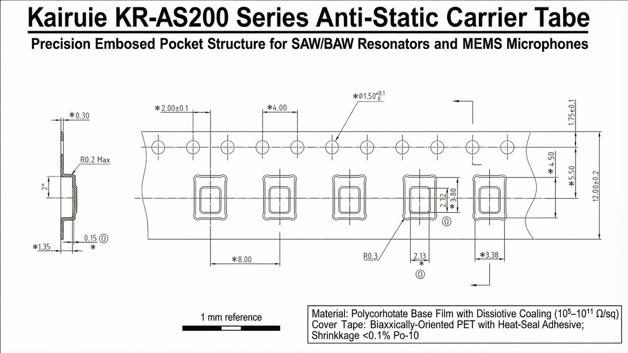
The choice of base material and anti-static grade directly influences the performance and safety of the packaged components. Acoustic chips are particularly susceptible to mechanical stress from pocket deformation and to ESD damage during automatic placement. The knowledge base at Kairuie defines three anti-static grades: Standard (>1012 Ω/sq), Anti-Static Dissipative (105–1011 Ω/sq), and Anti-Static Conductive (103–105 Ω/sq). For general SMT components, standard non-anti-static materials may suffice, but for MEMS microphones and resonators, the conductive or dissipative grades are imperative. Our KR-AC100 conductive tape ensures that any static charge generated during reel indexing or component singulation is bled to ground rapidly, protecting gate oxides and delicate membranes. Material selection also involves considering the feeding method: acoustic components are often handled by vibratory bowl feeders or tray feeders. Carrier tapes must maintain pocket integrity under high-speed operation. The exceptional dimensional stability of our polycarbonate tapes (<0.1% Po-10 shrinkage) guarantees that pocket centers remain precisely aligned with pick-and-place nozzles, reducing placement errors. Below is a summary of the anti-static grades and typical applications: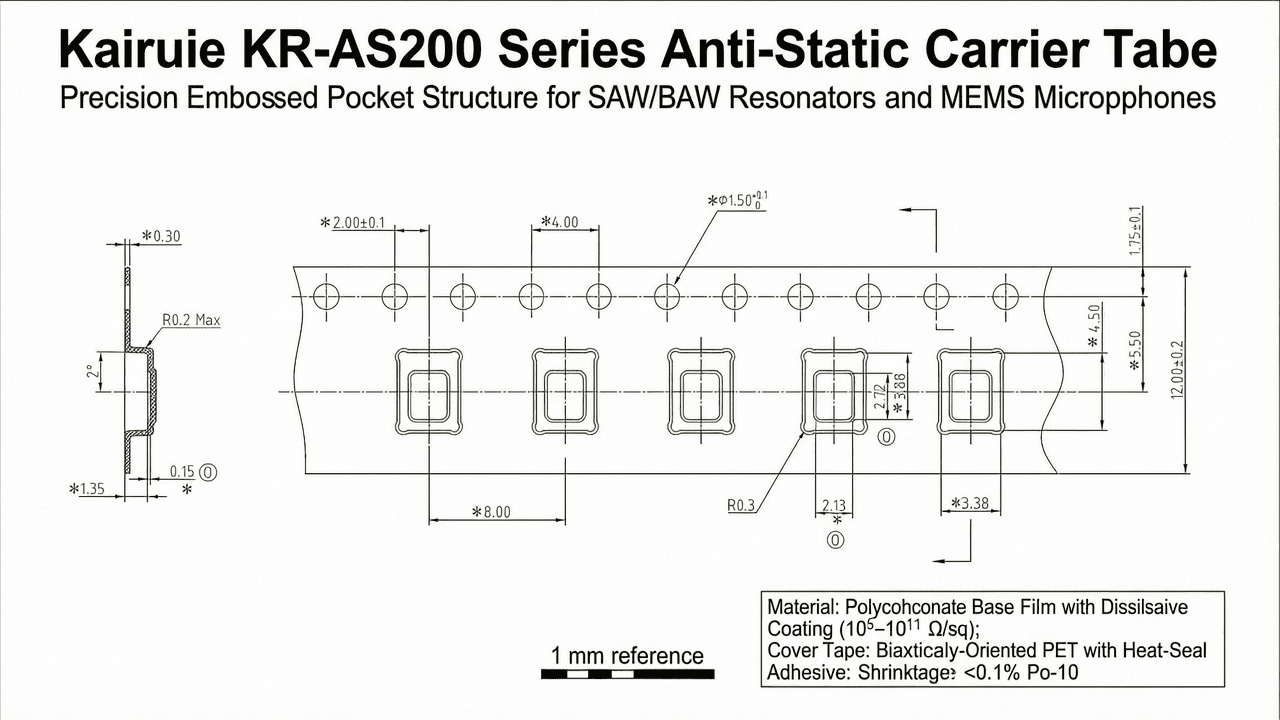
| Anti-Static Grade | Surface Resistivity | Typical Application |
|---|---|---|
| Standard (Non-Anti-Static) | >1012 Ω/sq | Mechanical parts, non-sensitive passives |
| Dissipative | 105–1011 Ω/sq | SAW/BAW resonators, most SMT ICs |
| Conductive | 103–105 Ω/sq | MEMS microphones, MOSFETs, ultra-sensitive chips |
Additionally, the carrier tape’s edge rails must offer sufficient stiffness to prevent bending during reeling. Kairuie’s tapes are designed with reinforced sidewalls and precise pocket depths (tolerance ±0.05 mm) to accommodate components as thin as 0.3 mm with coplanarity requirements.
3. Core Process Parameter Control
3.1 Carrier Tape Forming Parameters
The embossing process transforms flat film into three-dimensional pockets through a combination of heat, pressure, and time. For polycarbonate-based tapes, the recommended forming temperature range is 120–150°C. Lower temperatures result in incomplete pocket formation, rough surfaces, and stress whitening, while excessive temperatures can cause material degradation, discoloration, and dimensional instability. Pressure is typically maintained between 0.4 and 0.6 MPa, applied via servo-controlled forming punches. Dwell time, the duration the film is in contact with the heated tool, is set to 0.5–1.0 seconds. Optimizing these three parameters ensures crisp pocket geometries, smooth internal surfaces (Ra < 0.8 μm), and minimal residual stress. Kairuie employs real-time monitoring of cavity dimensions using automated optical inspection (AOI), with statistical process control (SPC) alarms triggered when dimensional drift exceeds ±0.04 mm.
3.2 Cover Tape Sealing Parameters
Sealing the cover tape to the carrier tape is a critical step that defines the peel strength. The heat-sealing process involves temperature, pressure, and sealing time. For our PET-based cover tapes, the sealing iron temperature is set between 150 and 180°C, depending on the adhesive formulation and production speed. The applied pressure is 0.3–0.5 MPa, and the dwell time is 0.3–0.8 seconds. Proper sealing ensures a peel force of 40–90 g as measured by a tensile tester at a 165–180° peel angle. Insufficient sealing temperature or time leads to low peel force and potential cover tape lifting; excessive parameters can cause adhesive flow into the pocket, contaminating the component or causing “blocking” that prevents smooth peel. Kairuie’s manufacturing lines feature closed-loop temperature controllers and roller gap sensors to maintain consistent nip pressure.
3.3 Process Window Optimization
Defining a robust process window is essential for high-yield production. We conduct full-factorial design of experiments (DOE) to map the interactions between forming and sealing parameters. The goal is to achieve a process capability index (Cpk) of at least 1.33 for critical characteristics: pocket dimensions, peel strength, and surface resistivity. For example, a typical DOE for the KR-AS200 series involves varying temperature (140 ± 10°C), pressure (0.5 ± 0.1 MPa), and dwell time (0.8 ± 0.2 s), measuring pocket depth and width. Response surface methodology identifies the optimal set point that minimizes variability. Once defined, the process parameters are locked into the machine recipe and monitored continuously. Environmental controls, including cleanroom class (ISO 7 or better) and humidity (30–60% RH), are also maintained to ensure static dissipation and material stability.
4. Common Issues & Troubleshooting
4.1 Troubleshooting Guide
Despite rigorous controls, production anomalies can occur. The following table lists common issues encountered with carrier tapes for acoustic components, their root causes, and recommended solutions.
| Symptom | Root Cause | Solution |
|---|---|---|
| Poor pocket definition, rounded corners, or incomplete forming | Forming temperature too low or insufficient pressure | Increase temperature within recommended range (120–150°C) and verify pressure (0.4–0.6 MPa); check heater functionality. |
| Excessive dust or particles inside pockets | Slitting debris, unclean tooling, or static attraction | Implement ionized air blow-off stations; maintain ISO 7 cleanroom; schedule regular tooling cleaning; use conductive-grade tape to minimize particle attraction. |
| Inconsistent peel strength (too high or too low) | Sealing temperature fluctuation or uneven pressure | Calibrate sealing iron temperature PID loops; check roller parallelism; verify cover tape adhesive lot consistency. |
| Component sticking to cover tape or pocket walls | Electrostatic charge buildup on the tape surface | Switch to conductive carrier tape (103–105 Ω/sq); ensure grounding of all equipment; increase ambient humidity to 40–60%. |
| Cover tape lifting or “peeling” during transportation | Contamination on sealing area, insufficient sealing energy, or adhesive degradation | Clean sealing bars with isopropyl alcohol; increase sealing time or temperature slightly; store tapes in controlled temperature/humidity before use. |
Addressing these issues promptly minimizes downtime and prevents defective products from reaching end-users. Kairuie’s technical support team provides on-site assistance and training to optimize processes.
5. Quality Inspection Standards
5.1 Incoming Quality Control (IQC)
Every production batch of raw materials—base film, cover tape, and reel components—undergoes strict IQC. Visual inspection under magnification checks for surface defects, discoloration, and contamination. Critical dimensions are measured using precision micrometers and vision systems: pocket length, width, depth (tolerance ±0.05 mm), pocket pitch (±0.1 mm), and overall tape width. Peel strength is tested on a tensile tester per EIA-481 using a 90° peel angle and a rate of 300 mm/min, with an acceptable range of 40–90 g. Surface resistivity is verified with a concentric ring electrode conforming to ASTM D257, ensuring compliance with the specified anti-static grade. Any non-conforming material is quarantined and returned to the supplier.
5.2 In-Process Quality Control (IPQC)
During carrier tape manufacturing, IPQC stations perform sampling every two hours or for every 500 meters of tape produced. At each check, five consecutive pockets are measured for depth and width using a calibrated vision system; the average and range are plotted on control charts. If the range exceeds 0.04 mm or the average drifts by more than ±0.03 mm from the target, the line is stopped for adjustment. Peel strength samples are taken from each reel: a 300 mm section is sealed with the specified cover tape, and peel force is measured. The Cpk for peel strength is maintained above 1.33. Additionally, particle counts are monitored via airborne particle counters in the cleanroom, with action limits at ≥352,000 particles/m³ for 0.5 µm and larger.
5.3 Reliability Testing
To ensure long-term performance under expected shipping and storage conditions, Kairuie conducts rigorous reliability tests on each product series. Accelerated aging is performed at 85°C and 85% relative humidity for 168 hours; after exposure, peel strength must remain within the original specification and visual inspection must show no delamination or corrosion. Thermal cycling from -40°C to +85°C for 100 cycles simulates extreme transport environments; dimensional stability and anti-static properties are re-checked. Transportation simulation according to ISTA 3A vibration and drop test protocols verifies that the tape-and-reel system can withstand typical logistics handling without component damage or cover tape opening. Additionally, outgassing tests per ASTM E595 are available for aerospace-grade applications, ensuring the tape does not contaminate sensitive components.
6. Selection Guide
6.1 Recommended Solutions by Component Type
Choosing the right carrier tape depends on the component’s sensitivity, size, and handling requirements. The table below provides a quick reference for selecting the appropriate Kairuie product series.
| Component Type | Recommended Kairuie Series | Anti-Static Grade | Base Material | Key Features |
|---|---|---|---|---|
| MEMS Silicon Microphones | KR-AC100 | Conductive (103–105 Ω/sq) | Polycarbonate | Ultra-low particle, precise pocket depth (±0.03 mm), ESD-safe |
| SAW/BAW Resonators | KR-AS200 | Dissipative (105–1011 Ω/sq) | Polycarbonate or Polystyrene | Low shrinkage, excellent dimensional stability, cleanroom-manufactured |
| High-Frequency ICs (RF chips) | KR-AS300 | Dissipative | Polycarbonate | Wide temperature range, compatible with high-speed assembly |
| Standard Chip Components (RLC) | KR-S Standard | Non-Anti-Static | Polystyrene | Cost-effective, general-purpose |
For applications requiring custom pocket geometries or special anti-static properties, Kairuie offers rapid prototyping and sampling within 5 working days. Customers can specify pocket dimensions, tape width (8–56 mm), and feeding direction. Our engineering team assists with finite element analysis (FEA) to optimize pocket design for stress-free component containment.
7. Conclusion
Acoustic chip resonators and silicon microphones represent the forefront of microelectronic integration, demanding packaging materials that deliver uncompromising cleanliness, electrostatic protection, and mechanical precision. Kairuie Electronic Materials Co., Ltd. addresses these challenges with a portfolio of anti-static carrier tapes whose material science, process controls, and rigorous quality assurance set new benchmarks for the SMT industry. By utilizing polycarbonate films with Po-10 shrinkage below 0.1%, achieving surface resistivities as low as 103 Ω/sq, and maintaining dimensional tolerances within ±0.05 mm, our KR-AC100 and KR-AS200 series consistently enable high-yield assembly of the most sensitive acoustic components. We invite engineers, procurement managers, and technical specialists to explore our full range of electronic packaging materials and to engage with our experts for tailored solutions. Visit www.kairuie.com to learn more about our innovations, request samples, or discuss your specific application requirements. Together, we can advance the reliability and performance of tomorrow’s electronic devices.


