凯瑞尔电子材料
1. Introduction
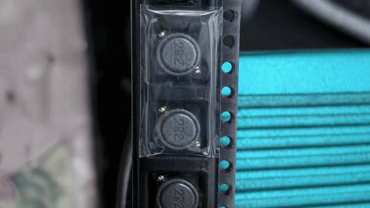
In the Surface Mount Technology (SMT) assembly process, traditional integrated inductors (also known as molded inductors) are essential passive components widely used in power management, filtering, and energy storage applications. Their compact size, typically ranging from 2520 to 1260 footprints, and ferrite-based construction make them susceptible to mechanical damage during high-speed tape-and-reel packaging. Edge chipping, defined as the fracture or breaking off of small pieces from the circumference of the inductor body, is a recurring defect that compromises electrical performance, solderability, and long-term reliability. This article explores the root causes of inductor edge chipping during high-speed taping and presents Kairuie Electronic Materials Co., Ltd.’s advanced cover tape solutions and process optimization strategies to mitigate these defects. We will examine the critical role of cover tape material properties, sealing parameters, and integrated inspection equipment—such as the Kairuie CT-1000 series cover tape placement system with CCD vision inspection and automatic reject removal—in ensuring zero-defect packaging for sensitive SMT components.
2. Product Structure & Material Composition
The cover tape (also called top tape or sealing tape) is a multi-layer engineered film that seals the component cavities in an embossed carrier tape, protecting inductors from environmental contamination and physical shock during transportation and automated pick-and-place. Kairuie’s KR-100 and KR-200 series cover tapes are specifically designed for high-speed, high-reliability applications where component edge chipping must be minimized. Their layer structure is engineered to provide optimal balance between adhesion strength, peel consistency, and stress distribution.
2.1 Layer Structure and Material Functions
Kairuie cover tape typically consists of three functional layers: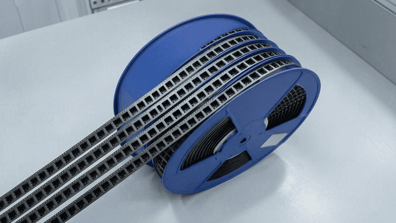
- Base Film (PET Layer): A biaxially oriented polyethylene terephthalate (PET) film with thickness options of 48 μm, 58 μm, or 75 μm. This layer provides mechanical strength, dimensional stability, and heat resistance during sealing. For inductor packaging, the 58 μm variant (KR-100-58) is recommended due to its optimal stiffness-to-flexibility ratio that reduces localized pressure on component edges.
- Anti-Static Coating: An integral or applied static dissipative layer with surface resistivity controlled between 10⁶ and 10⁹ Ω/sq, compliant with ANSI/ESD S541. This prevents electrostatic discharge (ESD) damage and dust attraction, which can exacerbate edge chipping by causing irregular adhesion.
- Heat-Activated Adhesive Layer: A proprietary acrylic-based adhesive with a melting point of 125°C and a thickness of 25–35 μm. It provides consistent bond strength to both polystyrene (PS) and polycarbonate (PC) embossed carrier tapes. The adhesive is formulated to yield a peel force of 30–70 g after sealing, as per EIA-481 standards. For inductors, a mid-range peel force of 40–50 g is preferred to avoid excessive tension during tape unwinding that could stress fragile edges.
Optionally, for self-adhesive (pressure-sensitive) cover tapes like the KR-200-SA series, a soft acrylic adhesive with a silicone release liner is employed. These tapes bond at room temperature, eliminating thermal stress during sealing—a key advantage for thermally sensitive ferrite inductors.
2.2 Key Material Parameters
| Parameter | KR-100-58 (Heat Seal) | KR-200-SA (Self-Adhesive) | Test Method |
|---|---|---|---|
| Total Thickness | 88 ± 5 μm | 92 ± 5 μm | ASTM D374 |
| PET Thickness | 58 μm | 58 μm | Optical Micrometer |
| Surface Resistivity | 1×10⁸ Ω/sq | 5×10⁷ Ω/sq | ASTM D257 |
| Peel Force (to PS carrier) | 45 ± 15 g | 50 ± 10 g (after 24h dwell) | EIA-481, 300 mm/min |
| Sealing Temperature | 140–160°C | Room Temp (20–25°C) | — |
| Width Compatibility | 8–56 mm (up to 88 mm custom) | 8–56 mm | — |
| Roll Length | 500 m / 1000 m | 200 m / 500 m | — |
For high-speed taping of integrated inductors, the KR-100 series with its controlled heat seal and anti-static properties is the primary recommendation, while the KR-200-SA serves applications where zero thermal input is critical, such as high-sensitivity ferrite cores that may micro-crack under heat.
3. Core Process Parameter Control
Precise control of the cover tape sealing process is the most direct lever to prevent edge chipping. The three key parameters—temperature, pressure, and dwell time—must be optimized relative to the carrier tape material, inductor size, and line speed. Kairuie’s extensive process studies have established recommended windows that minimize mechanical shock while ensuring a hermetic seal.
3.1 Sealing Temperature
For heat-seal cover tapes (KR-100), the sealing shoe temperature directly influences adhesive flow and bond formation. Recommended range: 140–160°C. Temperatures below 135°C result in incomplete adhesive activation, leading to weak bonds and potential tape lifting during transport, which can expose inductors to vibration-induced chipping. Above 165°C, excessive heat transfer may soften the carrier tape pockets and cause the inductor to adhere to the cover tape adhesive, creating a “capillary” effect that exerts uneven pull forces on the inductor edges during component removal. This is especially problematic for small inductors (e.g., 1608 size) where the surface area to volume ratio is high. For optimum results with KR-100-58 on PS carrier tapes, setpoint 150°C with a ±2°C tolerance is ideal, validated by thermal profiling of the sealing head.
3.2 Sealing Pressure
The pressure applied by the sealing shoe must be uniform across the tape width to avoid localized high-stress points. Recommended pressure range: 2.5–4.0 bar (0.25–0.4 MPa). Excessive pressure (>4.0 bar) compresses the carrier tape flange and can mechanically indent the inductor into the pocket bottom, transmitting force through the component to its corners, causing edge fracture. Insufficient pressure (<2.0 bar) leads to poor seal integrity and increased peel force variability. For KR-100-58 with 12 mm carrier tape, 3.0 bar yields a consistent peel force of 45 g. Kairuie’s CT-1000 placement system incorporates a digital pressure regulator with PID control, maintaining pressure within ±0.1 bar even at line speeds up to 80 pockets per minute.
3.3 Dwell Time
Dwell time—the duration the hot shoe remains in contact with the tape during sealing—directly affects heat transfer and adhesive curing. Recommended range: 0.3–0.8 seconds for continuous indexing taping machines. A dwell time shorter than 0.3 seconds may not allow full adhesive wet-out, causing weak seals; longer than 0.8 seconds can overheat the carrier, causing pocket deformation that misaligns the inductor and exerts lateral stress on its edges when the cover tape is applied. At 60 pockets/min, a dwell of 0.5 seconds is optimal. The CT-1000 uses servo-driven indexing with encoder feedback to synchronize dwell precisely, independent of line speed fluctuations.
3.4 Process Window Optimization
To establish a robust process window for a specific inductor, we recommend Design of Experiments (DOE) varying temperature and pressure while measuring defect rate and peel force. Kairuie’s application team provides on-site support using the CT-1000’s data logging capability to map optimal parameters. An example validated window for a 5.7×5.4 mm molded inductor in 12 mm PS carrier tape with KR-100-58: temperature 148°C, pressure 3.2 bar, dwell 0.55 seconds, resulting in defect rate < 50 ppm and peel force 46 ± 5 g.
4. Common Issues & Troubleshooting
| Symptom | Root Cause | Solution |
|---|---|---|
| Inductor edge chipping occurs randomly, mostly at pocket corners. | Sealing pressure too high or uneven, concentrating force on inductor edges through carrier tape deformation. |
|
| Chipping occurs primarily after long-term storage or transportation. | Cover tape peel force too high, causing excessive pull on inductors during tape unwinding in pick-and-place machines. |
|
| Edge chipping combined with visible adhesive transfer to inductor. | Sealing temperature too high, causing adhesive to flow onto component and create mechanical interlock. |
|
| Intermittent chipping correlated with cover tape misalignment. | Cover tape guiding inaccuracy causes it to shift relative to carrier tape, leading to inconsistent seal width and localized stress. |
|
| High edge chipping rate on small inductors (1608/2012 size). | Pocket geometry not optimized for component; pocket walls too tight, causing initial insertion damage that worsens during sealing. |
|
5. Quality Inspection Standards
Implementing strict quality checks at each stage of the taping process is critical to catching and eliminating defect sources before they propagate. Kairuie’s cover tape solutions are complemented by inspection protocols embedded in the CT-1000 and off-line testing procedures.
5.1 Incoming Quality Control (IQC)
Prior to use, all cover tape reels are subjected to:
- Visual Inspection: Under 10× magnification, check for gels, fisheyes, coating streaks, or foreign particles that could cause uneven adhesion. Acceptance criteria: zero defects per 25‑mm length based on AQL 0.65 per MIL‑STD‑1916.
- Dimensional Verification: Width measured with digital calliper to ±0.1 mm; thickness with micrometer in 5 evenly spaced points across the width to verify uniformity (<5% variation).
- Peel Strength on Reference Carrier: Ten samples sealed at specified parameters and peeled at 300 mm/min, 180° angle; average peel force must be within specified range and standard deviation <10%.
- Surface Resistivity: Tested per ASTM D257 at 23°C, 50% RH; must be within 10⁶–10⁹ Ω/sq.
5.2 In-Process Quality Control (IPQC)
During high-speed taping on the CT-1000 system:
- Sampling Frequency: Every 30 minutes or every 10,000 pockets, whichever comes first, an operator removes 5 sealed units for off-line inspection. Additionally, the CT-1000’s CCD system performs 100% in-line inspection.
- Acceptance Criteria: Seal width must be within ±0.2 mm of center; no void, wrinkle, or misalignment exceeding 0.3 mm. Peel force of sampled tapes must not drift beyond ±15% of initial value.
- Automatic Reject: The CT-1000’s vision algorithm detects edge chipping, seal defects, or missing components and triggers a pneumatic reject gate to divert defective pockets into a separate collection bin, while allowing good pockets to rewind seamlessly.
5.3 Reliability Testing
For qualification and periodic lot acceptance, packaged inductors undergo:
- Aging Test: Sealed tapes stored at 40°C/95%RH for 168 hours, then inspected for corrosion or tape degradation; peel force change <20%.
- High/Low Temperature Test: Exposed to –40°C for 2 hours and +125°C for 2 hours, repeated 5 cycles; no cracking, delamination, or seal failure.
- Transportation Simulation: ISTA 1A vibration and drop test; after testing, visual and peel force checks ensure no edge chipping or seal opening.
The CT-1000 automatically logs all inspection data and reject events, providing traceability and statistical process control (SPC) for continuous improvement.
6. Selection Guide
Choosing the right cover tape depends on inductor type, packaging speed, and environmental requirements. The table below summarizes Kairuie’s recommended cover tape series for typical application scenarios.
| Application Scenario | Recommended Cover Tape | Key Features & Value |
|---|---|---|
| Standard SMT inductors (2520–1260 size) in high-speed PS carrier tape, moderate volume. | KR-100-58 Heat Seal | Balanced stiffness; proven peel force control; anti-static. Compatible with CT-1000 CCD inspection for auto reject, reducing manual QC. |
| Ultra-small inductors (0603/0804) or high-sensitivity ferrite cores prone to thermal micro-cracks. | KR-200-SA Self-Adhesive | Room temperature application eliminates heat stress; consistent low peel force; ideal for applications where heat seal temperature would exacerbate edge chipping. Available with static dissipative liner. |
| Large power inductors (≥ 7 mm sq.) with heavier mass, requiring robust seal and peel. | KR-100-75 Heat Seal (thicker PET) | Higher mechanical strength prevents tape tearing during high-force peeling; distributes sealing pressure more uniformly over larger component area, reducing edge stress concentration. |
| High-reliability automotive/medical inductors requiring Class 1 cleanliness and traceability. | KR-100HC (Cleanroom-manufactured, with serialized barcode on reel) | Produced in ISO Class 7 cleanroom; ultra-low outgassing adhesive; barcode linked to CT-1000 logging for full process genealogy. |
| Mixed feeder lines where some components are highly ESD sensitive. | KR-100AS (Anti-static enhanced, surface resistivity <10⁹ Ω/sq) | Provides additional ESD protection beyond standard; helps maintain ESD-safe environment throughout PCB assembly. |
For applications requiring tape widths beyond 56 mm, Kairuie offers custom-built CT-1000 machines with width up to 88 mm and corresponding cover tape formats. Our application engineers can also assist in tailoring adhesive chemistry for unique carrier tape polymers or extreme temperature cycles.
7. Conclusion
Edge chipping of traditional integrated inductors during high-speed taping is a multi-factorial problem arising from material, process, and handling interactions. By implementing a holistic solution that combines optimized cover tape materials with intelligent process control and inspection, manufacturers can significantly reduce defect rates, improve yield, and ensure reliable component delivery to SMT lines. Kairuie Electronic Materials Co., Ltd. offers a complete package: the KR-100 and KR-200 series cover tapes engineered for minimal stress transmission, coupled with the CT-1000 integrated placement and inspection system that closes the loop on quality. The ability to switch between heat seal and self-adhesive modes on a single platform provides versatility, while CCD vision and automatic reject removal guarantee only defect-free product reaches the customer.
As a leader in SMT electronic packaging materials, Kairuie is committed to pushing the boundaries of precision and reliability. Our cover tapes comply with EIA-481 global standards and are trusted by leading electronics manufacturers worldwide. We invite industry professionals and technical partners to explore how our solutions can elevate your packaging process. Visit our website at www.kairuie.com for detailed specifications, application notes, and to request samples. Let’s work together to build more robust and efficient SMT manufacturing ecosystems.


