凯瑞尔电子材料
1. Introduction
In the surface-mount technology (SMT) landscape, molded inductors are indispensable passive components that deliver stable inductance, low DC resistance, and high current handling. Their reliable integration into automated pick-and-place systems hinges on flawless tape-and-reel packaging. However, as production speeds escalate, a persistent challenge emerges: chipping at the edges of the inductor body during high-speed taping. This defect not only yields immediate visual rejects but can propagate micro-cracks that compromise long-term reliability. Addressing this issue demands a systematic examination of the taping process, material properties, and inline quality control measures. Kairuie Electronic Materials Co., Ltd. has engineered a state-of-the-art tape-and-reel packaging system that integrates manual placement, CCD vision inspection, automatic reject removal, and dual-mode sealing to mitigate such defects. This article explores the root causes of molded inductor chipping in high-speed taping and presents a comprehensive strategy using Kairuie’s technology, optimized process parameters, superior cover tape materials, and rigorous inspection protocols to achieve near-zero defect packaging.
2. Product Structure & Material Composition
2.1 Machine Configuration and Sealing Technology
The Kairuie packaging platform is designed around a modular architecture that ensures precision and adaptability. At its core, the system features manual component placement eased by ergonomic fixtures, followed by an advanced CCD vision inspection station that captures high-resolution images of each inductor to detect edge chips, cracks, or misplacement before sealing. A pneumatic reject mechanism automatically diverts defective parts into a separate bin, while the sealing module applies either heat-seal or self-adhesive cover tape—switchable within seconds. The machine accommodates carrier tape widths from 8 mm to 56 mm (customizable up to 88 mm), making it versatile for tiny 0402 inductors up to larger 10 mm x 10 mm components. This dual-mode sealing capability allows manufacturers to select the most appropriate sealing method based on production speed and component fragility.
2.2 Cover Tape Layer Structure and Material Parameters
The cover tape plays a critical role in preventing chipping. Kairuie supplies cover tapes (both heat-seal and self-adhesive) that feature a multi-layer construction: a biaxially oriented PET base film, a specially formulated adhesive layer, and an optional antistatic treatment layer. The base film thickness is precisely controlled at 0.060 ± 0.005 mm to provide sufficient tensile strength without excessive stiffness that could transmit stresses to the inductor body. The heat-seal adhesive is an ethylene‑vinyl acetate (EVA) copolymer with a softening point of 110°C, while the self-adhesive version uses a pressure-sensitive acrylic with a peel adhesion of 0.8–1.2 N/25 mm. Surface resistivity for the antistatic variant is maintained between 10⁶ and 10⁹ Ω/sq, compliant with stringent ESD standards. These parameters are verified against EIA-481 guidelines, ensuring compatibility with standard feeders and high-speed SMT lines.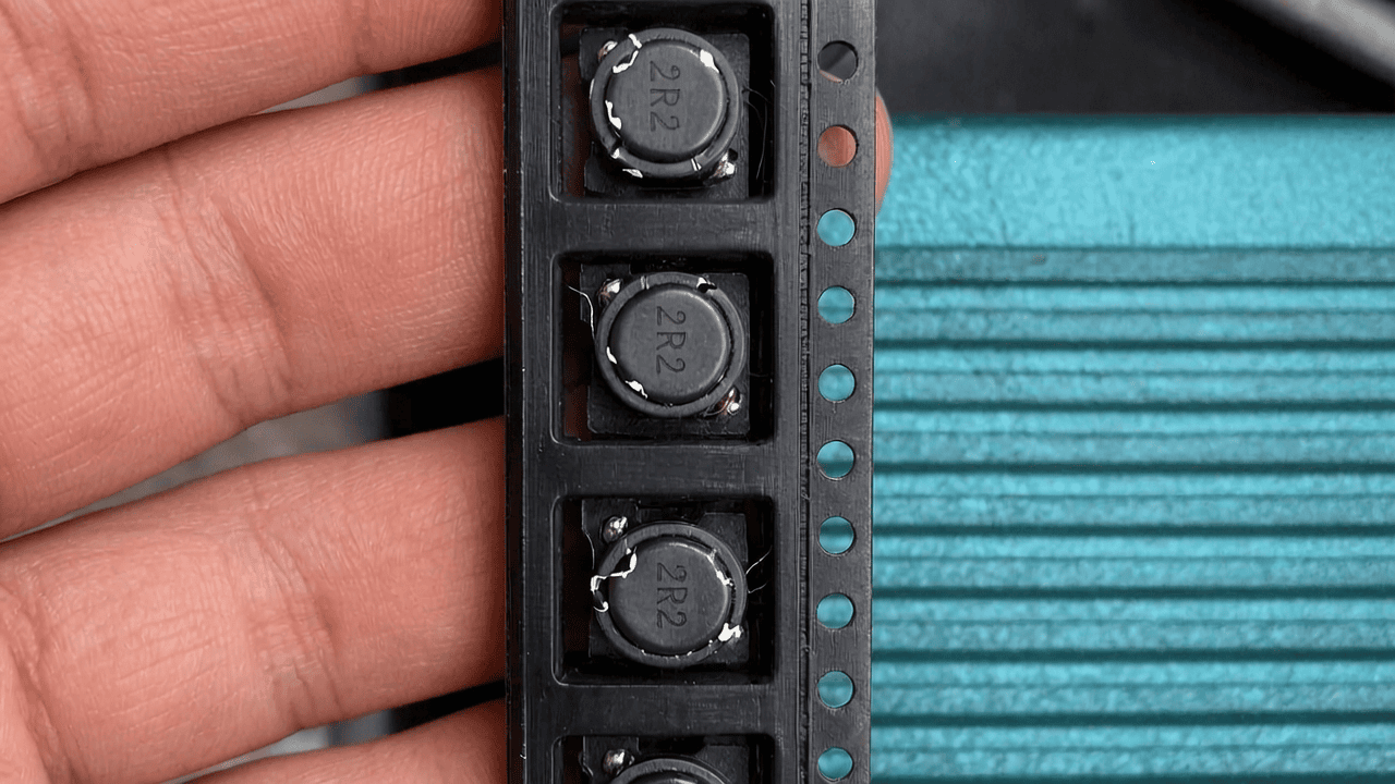
3. Core Process Parameter Control
3.1 Sealing Temperature Optimization
For heat-seal cover tape, temperature is the most influential parameter affecting both seal integrity and potential component damage. Kairuie’s system incorporates a closed-loop PID temperature controller ±1°C. Recommended sealing temperature ranges from 140°C to 160°C, with an optimal set point of 150°C for typical EVA‑based tapes. Below 140°C, incomplete melting of the adhesive results in weak seals and peeling force below the 0.5 N minimum specified by EIA-481, risking pocket opening during reeling or transportation. Above 160°C, excessive heat can soften the carrier tape pocket walls, causing deformation that pinches the inductor and induces edge chipping. In high-speed operations (over 60 pockets per minute), a temperature of 150°C combined with a 0.8‑second dwell time provides sufficient heat transfer without overheating the plastic. The dual-mode ability allows switching to self-adhesive tape for ultra-temperature-sensitive large inductors, eliminating thermal stress entirely.
3.2 Pressure and Time Settings
Sealing force and dwell time must be tightly controlled. The machine’s pneumatic press is adjustable from 0.2 MPa to 0.5 MPa. For molded inductors, we recommend a contact pressure of 0.3–0.35 MPa. Excessive pressure can directly crush the inductor body, especially at corners where stress concentrates, leading to visible chipping. Additionally, dwell time should be synchronized with the index speed: at a standard 40 ms indexing, a dwell time of 0.5–0.8 seconds ensures adequate bonding. The Kairuie system’s CCD inspection can detect orientation errors; a misaligned inductor may protrude slightly above the pocket, where the sealing jaw will exert concentrated force, causing edge fracture. By automatically rejecting such misoriented parts before the sealing station, the system prevents catastrophic chipping downstream.
4. Common Issues & Troubleshooting
| Symptom | Root Cause | Solution |
|---|---|---|
| Corner chipping on 50% of inductors after sealing | Excessive sealing pressure deforming the pocket and squeezing the component | Reduce pneumatic pressure to 0.3 MPa and verify jaw flatness. Inspect pocket dimensions; if worn, replace carrier tape reel. |
| Random micro-cracks visible only under 20x magnification | High feed speed causing abrupt start-stop cycles that shake the inductor against cavity walls | Lower indexing acceleration via servo parameter tuning. Upgrade to Kairuie’s anti-vibration transport path with compliant guides. |
| Chips appear near inductor top edge on one side only | Incorrect orientation of the inductor in the pocket; the tall side hits the sealing jaw first | Enable CCD vision inspection to check orientation; reject misoriented parts; improve operator training for manual placement. |
| Peel force too low, some pockets open; chipping later due to movement | Sealing temperature too low or inconsistent temperature distribution across the jaw | Verify temperature with a thermal imager; calibrate PID loop; ensure even heater contact; consider self-adhesive tape for faster cycles. |
| Static discharge causing chips to stick to cover tape, then secondary damage | ESD buildup from fast unwinding without ionization | Use Kairuie antistatic cover tape with surface resistivity < 10⁹ Ω/sq; install static eliminators near peel-off point. |
5. Quality Inspection Standards
5.1 Incoming Quality Control (IQC)
Before tape-and-reel processing, molded inductors undergo scanning acoustic microscopy (SAM) to ensure no internal delamination, and a 100% visual inspection under 10x magnification for edge chips larger than 0.05 mm. Carrier tape and cover tape are inspected per EIA-481: peel adhesion of cover tape is verified to be 0.5–1.5 N, and dimensional tolerances of pocket depth are held within ±0.03 mm. Kairuie’s machine is equipped with a built-in calibration routine that cross-checks tape dimensions using the CCD camera; any deviation triggers an alarm. This proactive IQC prevents the introduction of out-of-spec materials that could exacerbate chipping.
5.2 In-Process Quality Control (IPQC)
During production, the Kairuie system conducts continuous inline monitoring. The CCD vision module performs 100% inspection at a throughput of up to 80 pockets per minute. A sampling plan (MIL-STD-105 Level S‑3, AQL 0.65) calls for one sealed reel to be pulled every 30 minutes for off‑line peel test and manual microscope inspection. Acceptance criteria: zero chips > 0.1 mm and peel force within 0.45–1.5 N. Any reject triggers an immediate line stop and root cause analysis. This closed-loop feedback ensures that chipping events are caught near real‑time.
5.3 Reliability Testing
Finished reels are subjected to a series of reliability tests. A 168‑hour aging test at 85°C/85%RH follows J-STD-020 to assess seal integrity and chip growth under humidity. High/low temperature cycling from −40°C to +125°C for 500 cycles verifies that thermal expansion does not induce edge stresses. Lastly, a transportation simulation per ISTA 3A confirms that the packed inductors survive vibration and drops without developing new chips. Data from these tests are used to continuously refine process parameters.
6. Selection Guide
6.1 Recommended Cover Tape by Component Type
| Component Scenario | Cover Tape Type | Key Features & Compatibility |
|---|---|---|
| Small SMD inductors (e.g., 0603, 0.3 mm thick) | Heat‑seal, 0.048 mm PET | High tensile strength, precise sealing for thin pockets; validated for 150°C, 0.3 MPa; antistatic option available. |
| Larger power inductors (>5 mm height) | Self‑adhesive, 0.060 mm PET | Pressure‑sensitive acrylic adhesive avoids thermal stress; peel adhesion 0.9 N/25 mm; wider sealing window for robust pockets. |
| High‑speed lines (>70 pcs/min) | Heat‑seal with optimized adhesive | Quick bond in 0.4 s; compatible with Kairuie’s dual‑mode machine at high indexing; antistatic to prevent particle attraction. |
| LED and optical sensitive inductors | Transparent PET self‑adhesive | Allows post‑seal visual inspection; ESD safe; easily peelable without tearing. |
7. Conclusion
Chipping of molded inductors during high‑speed taping is a multifaceted challenge rooted in mechanical, thermal, and electrostatic interactions. By deploying Kairuie’s integrated packaging system—which marries manual placement, CCD vision inspection, automatic reject removal, and dual‑mode sealing—manufacturers can systematically eliminate the root causes. The synergy of precise process control (150°C, 0.3 MPa, 0.8 s dwell), advanced cover tape materials, and rigorous quality inspections creates a robust defense against edge defects. As a dedicated supplier of SMT electronic packaging materials, Kairuie Electronic Materials Co., Ltd. (www.kairuie.com) continues to innovate solutions that push the boundaries of yield and reliability. We invite industry peers to collaborate and exchange insights, driving the evolution of defect‑free taping processes.


