凯瑞尔电子材料
1. Introduction
In high‑density surface‑mount technology (SMT) assembly, the packaging of ultra‑small chip components such as 0201 (0.6×0.3 mm) and 01005 (0.4×0.2 mm) presents unique challenges. The cover tape, which seals the carrier tape pockets, plays a critical role in protecting these delicate inductors during storage, transport, and automatic feeding. Among its many performance characteristics, peel force stability directly influences component pick‑up reliability. Excessive or inconsistent peel force can cause picking errors—commonly known as “throwing”—where the placement head fails to extract a component, leading to machine stoppages, wasted parts, and reduced throughput. This article examines how cover tape peel force stability affects throwing rates for 0201 and 01005 chip inductors, and details how Kairuie’s engineered cover tapes, such as the KR‑CC‑0201‑A and KR‑CC‑01005‑H series, provide a robust solution. We will explore the material structure, critical process parameters, troubleshooting, quality standards, and selection guidelines, aiming to equip SMT engineers with actionable knowledge to enhance their production efficiency.
2. Product Structure & Material Composition
2.1 Layer Structure of Kairuie Cover Tapes
Kairuie’s cover tapes are multi‑layer composites designed to deliver precise and stable peel performance. A typical construction includes: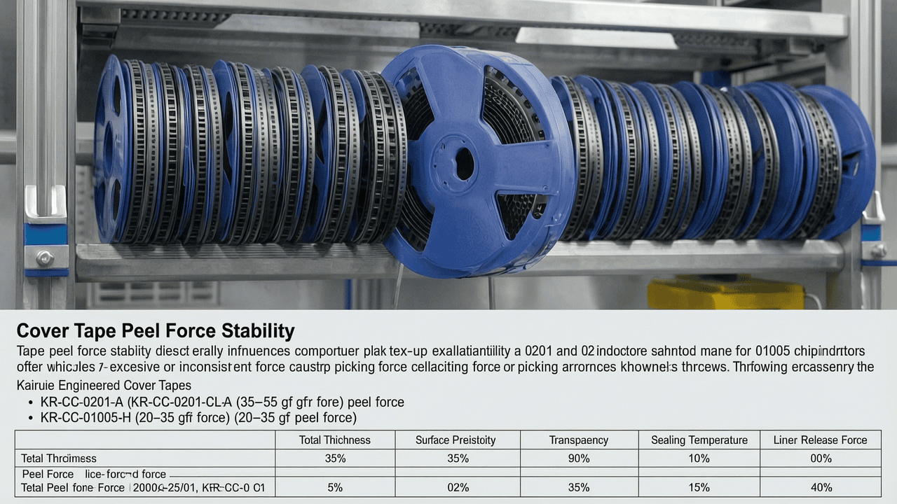
- Base Layer: Biaxially‑oriented polyester (BOPET) film with a nominal thickness of 0.060 ±0.005 mm. This provides mechanical strength and dimensional stability. For 01005 applications, a thinner 0.045 mm grade reduces bending stiffness, lowering the force required to peel the tape consistently.
- Antistatic Coating: An inner‑side conductive polymer layer with surface resistivity controlled to 106–108 Ω/sq, per ANSI/ESD S20.20, preventing electrostatic discharge that could cling tiny inductors to the pocket walls.
- Adhesive Layer: A heat‑activated (H/A) or pressure‑sensitive (PSA) adhesive. For 0201 inductors, Kairuie’s KR‑CC‑0201‑A employs a modified acrylic H/A adhesive that achieves a peel force window of 35–55 gf after sealing at 160–180°C. The 01005 series KR‑CC‑01005‑H uses a low‑tack PSA with a controlled peel force of 20–35 gf, critical for the featherweight components.
- Release Layer (optional): A thin silicone‑free coating on the tape’s outer surface prevents blocking during spooling.
2.2 Key Material Parameters
| Parameter | Unit | 0201 Cover Tape (KR‑CC‑0201‑A) | 01005 Cover Tape (KR‑CC‑01005‑H) |
|---|---|---|---|
| Total Thickness | mm | 0.080±0.010 | 0.065±0.010 |
| Peel Force (180° peel) | gf | 45±10 | 28±7 |
| Surface Resistivity | Ω/sq | 107–1011 | 107–1011 |
| Transparency | % | 85 | 85 |
| Sealing Temperature (H/A adhesive) | °C | 160–180 | – |
| Liner Release Force | gf | <10 | <10 |
These parameters ensure that the cover tape peels smoothly and consistently without “stick‑slip” that can vibrate the carrier tape and dislodge components. Kairuie’s proprietary adhesive formulation cross‑links during sealing to provide a predictable, time‑stable peel force across the reel’s entire length.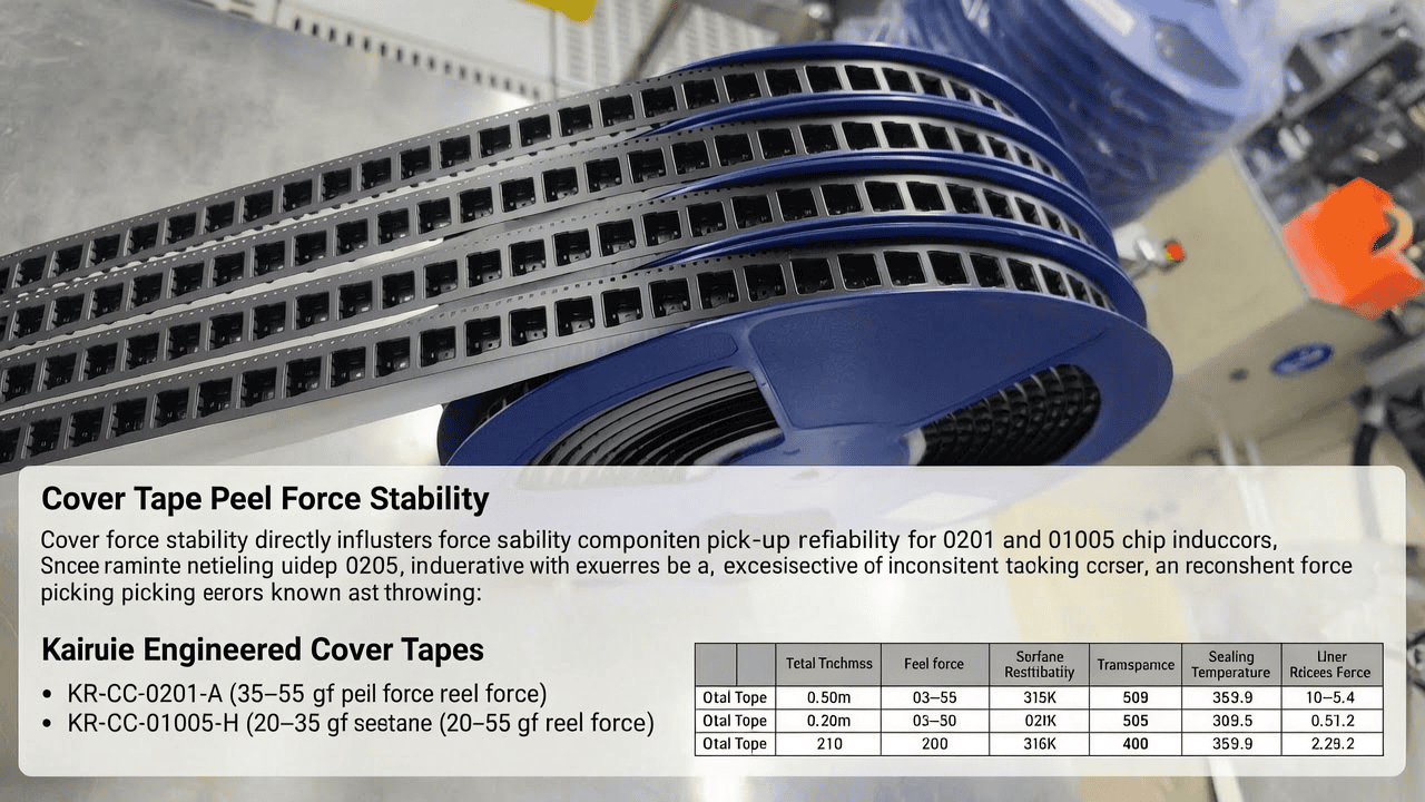
3. Core Process Parameter Control
3.1 Sealing Temperature and Pressure
For heat‑activated cover tapes like the KR‑CC‑0201‑A, sealing temperature and pressure must be tightly regulated. The recommended seal temperature is 165 ±15°C, with a dwell time of 0.3–0.5 seconds at a pressure of 2.5–3.5 bar. If the temperature is too low (<150°C), the adhesive does not fully wet the carrier tape, resulting in a peel force below the lower specification limit (LSL), which can cause the tape to lift prematurely during transport or feeder vibration, exposing pockets. Conversely, excessive temperature (>190°C) can over‑cure the adhesive, raising peel force above the upper specification limit (USL) and leading to pull‑ups where the placement head lifts the entire component strip. For 01005 inductors, uniform heat transfer is even more critical; Kairuie recommends a narrower temperature band of 160–175°C to achieve the ideal 20–35 gf peel force.
3.2 Peel Angle and Speed
Peel angle and speed during actual feeder operation also influence dynamic peel force. Most feeders peel the cover tape at an angle of 140°–160° and at the machine’s indexing speed. Kairuie has validated that the KR‑CC‑01005‑H tape maintains consistent peel force within ±5 gf at peel speeds up to 500 mm/s. To ensure compatibility, users should verify that the feeder’s peel blade is clean and free of burrs, which can cause micro‑snags and force spikes that dislodge 01005 inductors. Maintaining a peel angle as close to 180° as mechanically feasible minimizes the effective peel force and its variability.
3.3 Process Window Optimization
A design‑of‑experiments (DOE) approach can identify the optimum combination of temperature, pressure, and time. For instance, at Kairuie’s application lab, a central composite design for the KR‑CC‑0201‑A on a polycarbonate carrier tape revealed that a seal temperature of 172°C, pressure of 3.0 bar, and dwell of 0.35 s yielded a Cpk of 1.67 for peel force (center at 45 gf), effectively eliminating peel‑force‑related throwing. The process window is documented in the product datasheet and can be replicated on most commercial sealers.
4. Common Issues & Troubleshooting
| Symptom | Root Cause | Solution |
|---|---|---|
| Throwing rate >0.1% for 0201 inductors; frequent “pick‑up error” alarms | Peel force too high (>65 gf). Over‑sealing (temp too high or dwell too long). Adhesive residue on pocket edges. | Reduce sealer temperature by 5–10°C; check dwell time; inspect peel blade for adhesive build‑up; switch to KR‑CC‑0201‑A with lower nominal peel force. |
| Component escaping from pocket before pick‑up (01005) | Peel force too low (<15 gf); insufficient seal integrity; cover tape lifts due to vibration. | Increase sealing pressure and verify temperature; ensure carrier tape pockets are not deformed; consider KR‑CC‑01005‑H with higher adhesive coat weight. |
| Intermittent tape breakage during peel‑back | Mechanical stress from misaligned feeder; tape thickness variation; sharp peel blade edge. | Realign feeder; inspect tape path; replace peel blade; use KR‑CC‑01005‑H with improved tensile strength (>30 N/cm). |
| Static discharge causing components to stick to cover tape | Insulative inner surface; surface resistivity >1012 Ω/sq. | Verify antistatic coating integrity; ensure storage in dry conditions; use Kairuie tapes with permanent antistatic layer (e.g., KR‑CC‑0201‑A). |
| Peel force increases toward end of reel | Adhesive curing over time or moisture absorption; temperature gradient in sealing tool. | Use fresh stock within recommended shelf life; pre‑dry carrier tape; calibrate sealer temperature profile; choose KAIRUIE’s humidity‑resistant adhesive formulation. |
5. Quality Inspection Standards
5.1 Incoming Quality Control (IQC)
At Kairuie, every cover tape lot undergoes rigorous IQC before shipment. Visual inspection under 10× magnification checks for gel particles, fish‑eyes, and edge defects. Dimensional verification ensures width tolerance of ±0.1 mm and total thickness within ±10% of nominal. Peel force is tested on a tensile tester at 180° peel angle and 300 mm/min crosshead speed; a sample of 10 specimens per lot must have a mean within the specified range and a coefficient of variation (CV) <10%. Surface resistivity is measured per ASTM D257.
5.2 In‑Process Quality Control (IPQC)
For tape‑and‑reel operations using Kairuie cover tapes, IPQC checks should include peel‑force measurements every 2,000 pockets or once per reel change. A portable peel force tester (e.g., IMADA MX2-500N) can quickly validate the sealing quality. The acceptance criterion is that 90% of measurements fall within the control limits (typically USL / LSL based on the tape model) and no single value exceeds ±20% of the target. Additionally, component retention rate is verified by tapping a sealed carrier tape sample 10 times on a steel block; zero component fallout is required.
5.3 Reliability Testing
To ensure long‑term stability, Kairuie conducts accelerated aging tests: 1,000 hours at 85°C/85% RH, after which peel force must not drift by more than 15%. Thermal shock testing (−40°C to +85°C, 500 cycles) is performed to simulate storage and transport extremes. Transportation simulation per ISTA 3A validates that vibration and impact do not degrade tape seal integrity. All KR‑CC series cover tapes comply with such tests, providing confidence for global logistics.
6. Selection Guide
| Application Scenario | Component Size | Adhesive Type | Recommended Kairuie Product | Key Peel Force Range |
|---|---|---|---|---|
| High‑speed chip shooting (60,000 CPH+) | 0201 | Heat‑activated | KR‑CC‑0201‑A | 35–55 gf |
| Ultra‑miniature pick‑and‑place (01005) | 01005 | Pressure‑sensitive | KR‑CC‑01005‑H | 20–35 gf |
| Moisture‑sensitive components (MSL 3–5) | 0201/01005 | Heat‑activated, high barrier | KR‑CC‑0201‑A (with Al barrier laminate) | 35–55 gf |
| Cost‑optimized, general‑purpose | 0402 and larger | Heat‑activated | KR‑CC‑0402‑B | 40–70 gf |
When selecting a cover tape for delicate chip inductors, engineers must consider the pick‑up nozzle force (typically 10–30 gf for 01005) and ensure that the peel force is well below the nozzle’s grip limit. Kairuie’s technical support team can perform a tape‑feeder simulation test at www.kairuie.com to recommend the optimal product.
7. Conclusion
Peel force stability in cover tape is not merely a specification—it is a decisive factor in the assembly yield of precision chip inductors. For 0201 and 01005 components, even minute fluctuations can cascade into significant throwing rates, elevating cost and jeopardizing just‑in‑time production. Kairuie Electronic Materials Co., Ltd. addresses this challenge with patented adhesive technologies and tight manufacturing control, as exemplified by the KR‑CC‑0201‑A and KR‑CC‑01005‑H series. These tapes provide narrow peel force ranges, anti‑static protection, and robust mechanical properties that together drive throwing rates below 50 ppm. As devices continue to shrink, the collaboration between material suppliers and SMT engineers becomes ever more vital. We invite industry peers to visit www.kairuie.com to explore our full portfolio of SMT packaging solutions and to share insights on achieving zero‑defect assembly in the micro‑electronics era.


