凯瑞尔电子材料
1. Introduction
In surface mount technology (SMT), carrier tape is not merely a transport medium; it is a precision-engineered packaging component that directly influences pick-and-place accuracy, component integrity, and overall production yield. Anti-static carrier tape plays a critical role in protecting electrostatic discharge (ESD)-sensitive devices such as integrated circuits, LEDs, connectors, and passive components during automated assembly. The classification of anti-static grades—conductive, dissipative, and insulative—is fundamental to selecting the right tape for each application. This article provides a comprehensive technical analysis of Kairuie Electronic Materials Co., Ltd.’s anti-static carrier tape product line, covering material composition, process control, troubleshooting, quality inspection, and selection guidance. We will reference specific product configurations including separable-flange carrier tape, one-piece injection-molded carrier tape, and heat-seal cover tape, along with their anti-static specifications and dimensional parameters. Understanding these distinctions helps process engineers avoid costly ESD failures, line stoppages, and component damage while maintaining high throughput.
2. Product Structure & Material Composition
2.1 Carrier Tape Construction: Flange, Hub, and Pocket Design
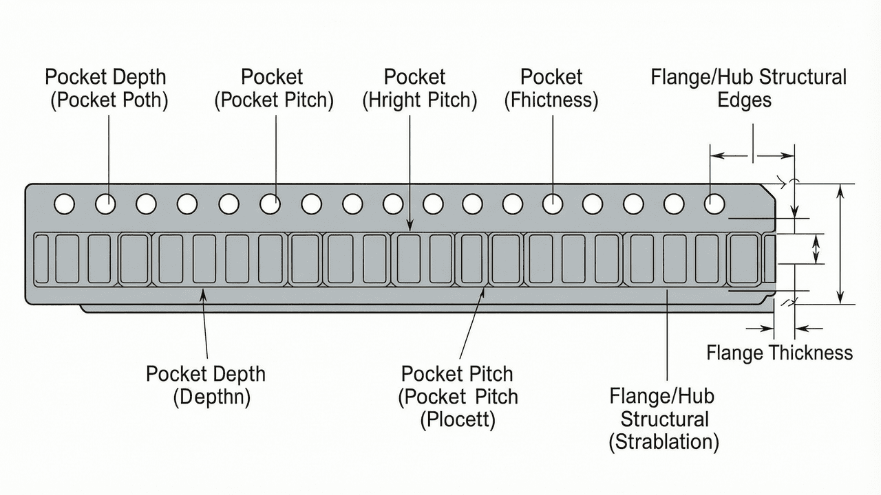
Carrier tape consists of a continuous strip with embossed pockets that hold individual components, and a flange or hub structure that interfaces with feeder mechanisms on pick-and-place machines. Kairuie offers two distinct structural designs. The first is the separable flange/hub type, in which the flange and hub are manufactured as separate components and can be assembled or disassembled easily. This feature allows users to replace hubs of different widths without changing the entire reel, reducing inventory cost and increasing flexibility. The second is the one-piece injection-molded flange/hub design, where flange and hub are molded as a single seamless unit. This construction provides higher mechanical strength and superior dimensional stability, making it ideal for high-speed automated packaging lines where reel run-out and wobble must be minimized. Both designs are available in blue, black, transparent, and pink (anti-static color) options, with base materials including PS (polystyrene), PC (polycarbonate), and ABS (acrylonitrile butadiene styrene). The choice of material affects rigidity, heat resistance, and static dissipative characteristics. For standard non-anti-static applications, PS offers an economical solution; for higher temperature resistance, PC is preferred; ABS provides a balance of toughness and cost. The pink color is specifically formulated to indicate anti-static properties, helping operators quickly identify ESD-safe reels on the production floor. Dimensional consistency of the pocket pitch and flange diameter is critical, as even minor variations can cause feeder jams or component mis-picks in high-speed SMT lines.
2.2 Cover Tape Material and Anti-Static Coating
The cover tape is heat-sealed onto the carrier tape after component loading, and its peel strength must remain stable throughout storage, transportation, and the SMT placement process. Kairuie’s cover tape is engineered for heated sealing, which provides more stable peel strength compared to pressure-sensitive adhesive systems. It is compatible with carrier tape materials including PC, PET, and PS, ensuring broad applicability across different component types and packaging requirements. Standard roll lengths are 300 meters per roll or 500 meters per roll, reducing changeover frequency and improving line efficiency. The cover tape is available in two anti-static configurations: single-sided anti-static and double-sided anti-static. In single-sided anti-static cover tape, the outer surface (the side exposed during peeling) has anti-static treatment with a surface resistivity of 10⁵~10¹¹ Ω/sq, while the component-contact side remains standard. Double-sided anti-static cover tape applies anti-static treatment to both surfaces, making it suitable for extremely sensitive components that require protection from static charges on both sides of the tape. This dual-side protection is critical for high-value MEMS sensors, RF devices, and other ESD Class 0 components. The cover tape typically consists of a base film, a heat-seal adhesive layer, and an optional anti-static coating. The base film provides mechanical strength and dimensional stability, while the adhesive layer determines sealing performance. Kairuie’s heat-seal adhesive is formulated to achieve consistent peel strength across a wide temperature range, reducing sensitivity to minor process fluctuations.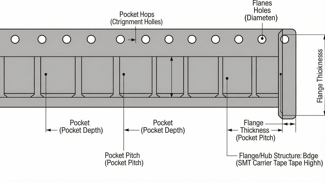
2.3 Anti-Static Grade Definitions and Surface Resistivity
The surface resistivity of a material determines its anti-static classification. According to industry standards such as ANSI/ESD S20.20 and IEC 61340-5-1, materials are classified as conductive, dissipative, or insulative based on surface resistivity. Conductive materials have surface resistivity below 10⁴ Ω/sq, dissipative materials fall in the range of 10⁴ to 10¹¹ Ω/sq, and insulative materials exceed 10¹¹ Ω/sq. Kairuie’s anti-static carrier tape and cover tape are designed to operate in the dissipative range of 10⁵~10¹¹ Ω/sq, which safely bleeds off static charges without the risk of rapid discharge that could damage components. The following table summarizes the anti-static grade specifications available in the Kairuie product line:
| Grade | Surface Resistivity | Application |
|---|---|---|
| Single-Sided Anti-Static | 10⁵~10¹¹ Ω/sq | Outer surface of cover tape is anti-static; component-contact side is standard |
| Double-Sided Anti-Static | 10⁵~10¹¹ Ω/sq | Both sides are anti-static — suitable for extremely sensitive components |
| Standard (Non-Anti-Static) | Greater than 10¹² Ω/sq | Non-ESD-sensitive components; cost-effective for general packaging |
It is important to note that the terms ‘conductive grade’ and ‘dissipative grade’ are sometimes used interchangeably in colloquial SMT discussions, but strictly speaking, conductive grade implies surface resistivity below 10⁴ Ω/sq, while dissipative grade is 10⁴~10¹¹ Ω/sq. Kairuie’s anti-static products are dissipative, which is the preferred range for component packaging because it prevents static accumulation while avoiding the risk of a too-rapid discharge. For applications requiring true conductive grade (below 10⁴ Ω/sq), custom formulations may be evaluated, but most SMT components are sufficiently protected within the dissipative range. Surface resistivity should be verified using a concentric ring probe per ASTM D257 or IEC 61340-2-3, and measurements should be taken at multiple points across the tape width to ensure uniformity.
3. Core Process Parameter Control
3.1 Sealing Temperature and Dwell Time
For heat-seal cover tape, sealing temperature and dwell time are the two most critical parameters affecting peel strength. The recommended sealing temperature range for Kairuie cover tape on PS carrier tape is 150°C to 170°C; for PC carrier tape, 160°C to 190°C; and for PET carrier tape, 150°C to 180°C. These ranges ensure that the heat-seal adhesive layer achieves proper flow and bonding without degrading the carrier tape material or the cover tape film. Dwell time should be set between 0.3 and 0.8 seconds, depending on sealing head design and line speed. If temperature is too low or dwell time too short, the adhesive does not fully wet the carrier tape surface, resulting in low peel strength and potential cover tape lifting during transportation or placement. Conversely, excessive temperature or prolonged dwell time causes the adhesive to over-cure or the carrier tape to deform, leading to peel strength that is too high or inconsistent. A high peel strength may cause component pickup issues, as the placement nozzle must apply additional force, risking component damage or tape tearing. It is recommended to calibrate the sealing head temperature with a thermocouple at least once per shift to ensure accuracy within ±2°C. The actual sealing temperature at the interface may differ from the setpoint due to thermal lag, so validation runs are essential.
3.2 Sealing Pressure and Peel Strength Stability
Sealing pressure directly influences the contact area between the cover tape and the carrier tape sealing rails. Recommended pressure ranges from 2.0 to 5.0 kg/cm². Insufficient pressure results in incomplete sealing, with microscopic gaps that allow moisture ingress or cover tape peeling at low force. Excessive pressure can crush the carrier tape pockets or cause the adhesive to squeeze out, contaminating the sealing area and creating variable peel strength. The target peel strength for most SMT applications is typically 20 to 80 grams per standard peel test method (e.g., 90° peel at 300 mm/min), though specific values should be validated per component and tape configuration. Kairuie’s heat-seal cover tape is designed to provide stable peel strength within this range when process parameters are properly set. Operators should perform peel strength testing at machine start-up and after any parameter change to confirm stability. Peel strength should be tested on at least 5 samples per reel, with the average and range recorded. A peel strength range of less than 15 grams between minimum and maximum indicates good process control. Pressure uniformity across the sealing width is also critical; uneven pressure can cause one side of the cover tape to peel easily while the other side remains tightly bonded, leading to skewed pickup.
3.3 Process Window Optimization
Optimizing the process window involves balancing temperature, pressure, and dwell time to achieve a robust sealing process. A recommended approach is to use a Design of Experiments (DOE) methodology. Start with the median values: temperature 165°C (for PS carrier), pressure 3.5 kg/cm², and dwell time 0.5 seconds. Run a peel strength test on at least 10 samples. If peel strength is below the lower limit, increase temperature by 5°C or extend dwell time by 0.1 second. If peel strength is above the upper limit, decrease pressure by 0.5 kg/cm² or reduce temperature by 5°C. After each adjustment, allow the sealing head to stabilize for 5 minutes before retesting. The final process window should provide a minimum Cpk of 1.33 for peel strength. It is also essential to monitor ambient humidity, as high humidity can affect static dissipative performance and adhesive behavior. Recommended storage conditions for cover tape are 20°C to 25°C and 40% to 60% relative humidity, and rolls should be kept in original packaging until use. Additionally, line speed affects the effective dwell time; at high speeds above 30 m/min, the dwell time may need to be increased or a preheating stage added to ensure consistent sealing. Validation runs should be performed at the maximum production speed to confirm process robustness.
4. Common Issues & Troubleshooting
The following table lists typical problems encountered during carrier tape and cover tape usage in SMT packaging, along with their root causes and recommended solutions.
| Symptom | Root Cause | Solution |
|---|---|---|
| Cover tape lifts from carrier tape during transportation | Insufficient sealing temperature or pressure; adhesive not fully activated | Increase sealing temperature by 5°C and verify pressure is within 2.0-5.0 kg/cm²; re-validate peel strength |
| Peel strength too high, causing component pickup failures | Excessive sealing temperature or dwell time; adhesive over-cured | Reduce temperature by 5°C or shorten dwell time by 0.1 s; check for carrier tape deformation |
| Component damage from electrostatic discharge (ESD) | Incorrect anti-static grade selected; surface resistivity out of specified range | Switch to double-sided anti-static cover tape and dissipative carrier tape; verify surface resistivity is 10⁵~10¹¹ Ω/sq |
| Reel wobble or poor tracking in high-speed feeder | Dimensional instability from non-one-piece flange/hub design | Replace with Kairuie one-piece injection-molded flange/hub carrier tape for better concentricity |
| Cover tape telescoping or misalignment on reel | Improper winding tension or hub width mismatch | Use separable flange/hub design to adjust hub width; ensure uniform winding tension during spooling |
5. Quality Inspection Standards
5.1 Incoming Quality Control (IQC)
Upon receipt of carrier tape and cover tape, incoming inspection should verify visual appearance, dimensions, and peel strength. Visual inspection checks for surface defects such as scratches, contamination, discoloration, or incomplete anti-static coating. Dimensional checks include pocket depth, pocket width, pitch, and overall tape width, using calibrated optical measurement systems or micrometers. For Kairuie carrier tape, typical dimensional tolerances are ±0.1 mm for pocket dimensions and ±0.2 mm for tape width. Peel strength testing is performed on heat-sealed samples using a tensile tester with a 90° peel angle and 300 mm/min speed. The acceptance criterion is that the average peel strength of at least 10 samples falls within the specified range, and the standard deviation is less than 10% of the mean. Surface resistivity of anti-static tape is measured using a concentric ring probe per ASTM D257 or IEC 61340-2-3, and must be within 10⁵~10¹¹ Ω/sq for both single-sided and double-sided grades. For cover tape, the anti-static coating must be uniform across the entire width, with no uncoated streaks. Incoming lots should be accompanied by certificates of analysis (COA) from Kairuie, documenting batch-specific test results.
5.2 In-Process Quality Control (IPQC)
During the packaging process, IPQC should include sampling at defined frequencies. For high-volume production, sample at least 5 carrier tape pockets per 1,000 components loaded, or every 30 minutes, whichever occurs first. Each sample should be inspected for pocket fill accuracy, cover tape sealing width, and peel strength. Sealing width should be consistent, typically 0.5 to 1.0 mm on each side of the pocket, with no adhesive bleeding into the pocket area. Peel strength should be tested on one sample from each new reel of cover tape or after any parameter adjustment. Acceptance criteria: 100% of sampled pockets must meet dimensional specifications, and peel strength must remain within the validated control limits. Statistical process control (SPC) charts should be maintained for peel strength and sealing temperature to detect trends before they become defects. Operators should also visually inspect for any cover tape lifting, wrinkling, or misalignment at the sealing station. Any deviation should trigger immediate line stoppage and corrective action, with records kept for traceability.
5.3 Reliability Testing
Reliability testing ensures that carrier tape and cover tape maintain performance throughout the supply chain. Aging test: samples are stored at 60°C for 168 hours, after which peel strength and surface resistivity are re-tested; change in peel strength should be less than ±20% of initial value, and surface resistivity must remain within specification. High/low temperature cycling: samples are subjected to -40°C for 30 minutes followed by 85°C for 30 minutes, for 50 cycles; no cover tape lifting, cracking, or delamination is allowed. Transportation simulation: per ISTA 2A or ASTM D4169, samples are subjected to vibration and drop tests; after simulation, the carrier tape must maintain pocket geometry, and cover tape peel strength must not degrade beyond the acceptable range. Additionally, anti-static tape should be tested for static decay time (less than 2 seconds from 1000V to 100V) per MIL-PRF-81705, though this is a more advanced test for critical applications. These reliability tests should be performed on a quarterly basis or whenever there is a material or process change. Kairuie provides technical support for designing custom reliability test plans tailored to specific end-use environments.
6. Selection Guide
Selecting the correct carrier tape and cover tape configuration depends on the component type, ESD sensitivity, and production line requirements. The following table provides a comparison of Kairuie product options for different application scenarios. For standard passive components that are not ESD-sensitive, a cost-effective PS separable flange/hub carrier tape with standard cover tape may suffice. For high-speed lines running small ICs, the one-piece injection-molded design reduces reel wobble and ensures precise pocket positioning. For extremely sensitive components, double-sided anti-static cover tape and conductive-grade dissipative carrier tape provide maximum ESD protection. When frequent hub width changes are required, the separable flange/hub design offers unmatched flexibility without sacrificing performance.
| Application Scenario | Component Type | Recommended Carrier Tape | Recommended Cover Tape | Key Reason |
|---|---|---|---|---|
| Standard passive components (resistors, capacitors) | Non-ESD-sensitive | PS separable flange/hub, standard anti-static | 300 m/roll standard cover tape, single-sided anti-static optional | Cost-effective, adequate protection |
| High-speed automated packaging of small ICs | Mildly ESD-sensitive | One-piece injection-molded flange/hub, PC material, dissipative grade | 300 m/roll single-sided anti-static cover tape | Dimensional stability for high-speed feeding, basic ESD protection |
| Extremely sensitive components (MEMS, RF, LED) | ESD Class 0 or 1 | One-piece injection-molded flange/hub, conductive-grade dissipative carrier tape | 500 m/roll double-sided anti-static cover tape | Both sides anti-static, stable peel strength, reduced changeovers |
| Mixed component widths requiring frequent hub changes | Various | Separable flange/hub carrier tape, ABS material | 300 m/roll or 500 m/roll as needed | Hub width replaceable without changing reel, flexibility |
For all applications, it is recommended to verify surface resistivity of the selected anti-static grade (10⁵~10¹¹ Ω/sq) and confirm peel strength compatibility with the pick-and-place machine. Kairuie’s technical team can assist with validation testing and provide samples for evaluation.
7. Conclusion
Kairuie Electronic Materials Co., Ltd. offers a comprehensive range of anti-static carrier tape and cover tape solutions that address the diverse needs of SMT electronic packaging. From separable flange/hub designs that provide flexibility to one-piece injection-molded structures that ensure high-speed dimensional stability, and from single-sided to double-sided anti-static cover tape with surface resistivity of 10⁵~10¹¹ Ω/sq, the product line delivers precision, temperature resistance, and reliability. The critical process parameters of sealing temperature, pressure, and dwell time can be optimized to achieve stable peel strength, while robust quality inspection standards ensure incoming, in-process, and reliability performance. Understanding the difference between conductive, dissipative, and insulative grades is essential for protecting ESD-sensitive components and maintaining production efficiency. We invite industry peers, SMT process engineers, and packaging specialists to explore our technical resources and product datasheets at www.kairuie.com. We welcome opportunities to exchange knowledge, collaborate on custom packaging solutions, and contribute to the advancement of ESD-safe electronic component handling. Please contact our technical support team to discuss your specific application requirements or to request samples for evaluation.


