凯瑞尔电子材料
1. Introduction
In the realm of Surface Mount Technology (SMT), the pursuit of zero-downtime production is the holy grail of manufacturing efficiency. As component sizes shrink to 01005 and below, and placement speeds exceed 10 components per second, the fragility of the supply chain—specifically the continuity of component feeding—becomes a critical bottleneck. The process of joining two reels of carrier tape, known as splicing, is no longer a manual ancillary task; it is a core engineering discipline that dictates the Overall Equipment Effectiveness (OEE) of the production line.
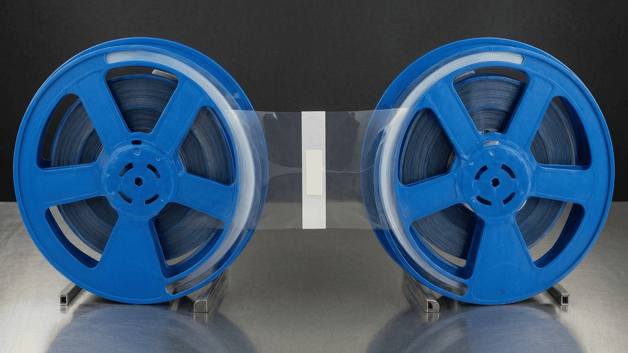
This article delves into a pivotal debate in modern SMT packaging materials: the choice between Split-Type and Integrated adhesive splicing systems (often referred to technically as ‘Adhesive Trays’ or splicing platforms). While both aim to achieve a seamless connection between an expiring reel and a new one, their underlying mechanics, material composition, and impact on process stability differ significantly. Drawing upon the technical expertise of Kairuie Electronic Materials Co., Ltd., we will explore how selecting the correct splicing architecture—specifically tailored to your feeder types and component characteristics—can prevent costly feeder jams, reduce component waste, and stabilize pick-and-place accuracy.
We will dissect the material science behind high-performance splicing tapes, analyze the thermodynamic variables affecting bond strength, and provide a rigorous framework for troubleshooting common defects. Whether you are managing high-speed chip mounters or handling delicate ICs, understanding the nuances of these two technologies is essential for maintaining a competitive edge in electronics manufacturing.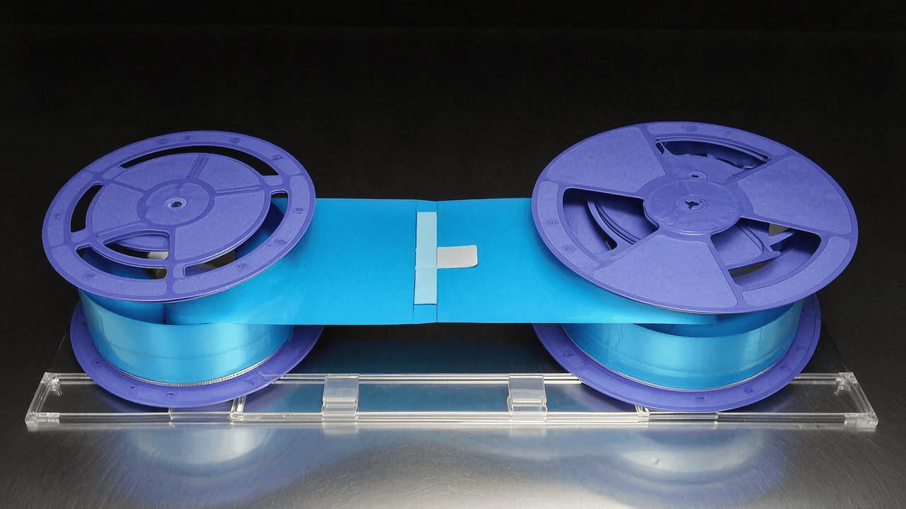
2. Product Structure & Material Composition
The foundation of any reliable splicing operation lies in the precise engineering of the adhesive material and the mechanical interface (the jig or tray) used to apply it. At Kairuie, our product lines are categorized into the KR-ST Series (Split-Type) and the KR-IT Series (Integrated). Understanding the layer structure of the tapes used in these systems is vital for Process Engineers.
2.1 Multi-Layer Architecture of Splicing Tapes
Professional-grade splicing tapes, such as the Kairuie KR-SP150 model, are not simple pressure-sensitive adhesives; they are multi-layered composite structures designed to withstand the dynamic stresses of high-speed unwinding.
- Base Layer (Backing Material): Typically composed of Polyester (PET) or Polyimide (PI). For standard applications, we utilize a 50μm PET film which offers an optimal balance of tensile strength (>100 MPa) and flexibility. For high-temperature applications involving lead-free reflow profiles (up to 260°C), the KR-SP-HighTemp variant employs a 25μm Polyimide backing.
- Adhesive Layer: This is the critical interface. We generally specify solvent-based Acrylic adhesives for their aging resistance, or Silicone-based adhesives for extreme temperature scenarios. The coating thickness is controlled within a tolerance of ±2μm to ensure consistent bonding without excessive bleed (oozing).
- Release Liner: A dual-sided release system is often employed in integrated solutions to protect the adhesive until the exact moment of contact.
2.2 Structural Differences: Split vs. Integrated
The distinction between the two systems lies primarily in the mechanical jig (‘Tray’) design and how the adhesive is applied to the carrier tape butt joint.
| Feature | Split-Type System (KR-ST) | Integrated System (KR-IT) |
|---|---|---|
| Mechanism | Uses separate top and bottom jigs. The bottom jig holds the tape in place via pins/clamps, while the top jig applies the adhesive patch. | A single, unified fixture that aligns both tapes simultaneously and applies adhesive (often pre-loaded or single-sided) in one closing motion. |
| Alignment Method | Relies on visual alignment marks (sprocket holes) and operator skill. High dependency on registration pin precision. | Features fixed guide rails and automatic registration pins that force alignment upon closure. |
| Adhesive Coverage | Usually applies adhesive to the top side only (covering the joint) or uses a ‘sandwich’ method manually. | Often utilizes a ‘H-back’ or full-coverage patch that wraps around the splice point for maximum tensile distribution. |
2.3 Key Material Parameters
When selecting materials from the Knowledge Base, engineers must pay close attention to the following specifications found in the Kairuie Product Datasheet v4.0:
- Thickness: Total thickness should range between 60μm and 100μm. Thicker patches (>120μm) risk jamming in narrow feeder gears (e.g., Fuji NXT feeders).
- Holding Power (Peel Strength): Must be between 800g/25mm and 1200g/25mm (180° peel test). Values lower than 600g result in ‘tape pop-off’ during acceleration; values higher than 1500g make the splice difficult to remove or cause excessive dust accumulation on the sprocket holes.
- Surface Resistivity: Critical for ESD safety. Must be in the range of 10^6 to 10^9 Ohm/square to prevent static charge buildup that could damage MOSFETs or CMOS devices.
3. Core Process Parameter Control
Achieving a ‘factory-floor invisible’ splice—one that passes through the feeder without triggering a sensor or causing a placement error—requires strict control over environmental and mechanical parameters. The adhesive bonding process is a physicochemical reaction influenced heavily by ambient conditions.
3.1 Temperature Control
Temperature is the most significant variable affecting the viscosity and wetting capability of acrylic adhesives.
Recommended Range: 20°C – 25°C (68°F – 77°F).
Technical Impact:
At temperatures below 15°C, the adhesive enters a glassy state, reducing its surface energy. This leads to poor ‘wetting’ on the carrier tape surface, resulting in weak initial tack. Conversely, temperatures exceeding 30°C can cause the adhesive to become overly aggressive, leading to ‘stringing’ when the protective liner is removed, or oozing into the sprocket holes (which must be kept clear for feeder sensor counting). For the KR-IT-300 integrated system, we recommend storing the adhesive trays in a temperature-controlled cabinet prior to use to stabilize the glue rheology.
3.2 Pressure Application
Pressure ensures intimate contact between the adhesive and the substrate, allowing van der Waals forces to engage fully.
Recommended Range: 0.4 MPa – 0.6 MPa (applied uniformly via roller or press plate).
Technical Impact:
Insufficient pressure leaves microscopic air voids (micro-bubbles) at the interface. These voids act as stress concentrators. When the tape undergoes the sharp bending radius of a feeder wheel (often < 5mm), these voids propagate, causing delamination. In Split-Type systems, operators often rely on hand pressure using a roller (e.g., a 3-inch hard rubber roller). We recommend a minimum of 3 passes with firm downward force. Integrated systems typically utilize a cam-lock mechanism that delivers consistent, repeatable pressure, eliminating human error variance.
3.3 Dwell Time (Curing)
While PSA (Pressure Sensitive Adhesive) bonds instantly, the bond reaches its ultimate strength after a period known as ‘wet-out’.
Recommended Range: Minimum 15 minutes before high-speed running (>5 m/min).
Technical Impact:
If the line is started immediately after splicing (especially in cold environments), the shear strength may be 30% lower than the rated value. This poses a risk of the splice snapping under the inertia of a heavy reel (e.g., a full reel of ceramic capacitors). Best practice dictates performing splices during the previous changeover cycle or allowing a ‘rest’ period for the splice.
4. Common Issues & Troubleshooting
Even with premium materials like those supplied by Kairuie, process deviations occur. The following table outlines the most frequent failure modes observed in SMT lines utilizing adhesive splicing systems, providing root cause analysis and corrective actions.
| Symptom | Root Cause Analysis | Solution & Corrective Action |
|---|---|---|
| Feeder Alarm: ‘No Component’ or ‘Cover Tape Open’ | 1. Excessive Splice Thickness: The combined thickness of the double-layered tape exceeds the feeder sensor gap tolerance (typically >0.15mm total deviation). 2. Misalignment: The splice creates a lateral offset, causing the cover tape edge to miss the peel-back knife. 3. Adhesive Oozing: Glue has contaminated the optical sensor window. |
1. Switch to Ultra-Thin Patch (e.g., KR-Patch-UT, 50µm): Reduce material stack-up. 2. Utilize Integrated Jig (KR-IT): Enforce rigid mechanical alignment. 3. Optimize Pressure: Reduce dwell time of the press to minimize squeeze-out; check adhesive viscosity specs. |
| Component Pick-up Failure (Vacuum Nozzle Miss) | 1. Vertical Displacement (Step Height): The bottom carrier tapes are not perfectly butted, creating a ‘bump’ or ‘valley’. 2. Tape Lifting: The adhesive bond pulls the carrier tape upward (tenting) due to shrinkage stress. |
1. Bottom-Side Reinforcement: Apply a stiffening patch (PET strip) to the bottom of the carrier tape before splicing the top. 2. Low-Shrinkage Backing: Specify tapes with dimensionally stable PET backings (shrinkage rate <0.5%). |
| Splice Breakage During Acceleration | 1. Insufficient Overlap Area: The patch was too short (<15mm). 2. Contaminated Surface: Dust or oil on the carrier tape prevented adhesion. 3. Brittle Adhesive: Material expired or stored in low humidity. |
1. Increase Overlap: Ensure minimum 20mm overlap on each side of the cut. 2. IPA Cleaning: Wipe carrier tape with lint-free cloth dampened with Isopropyl Alcohol before applying patch. 3. FIFO Inventory: Check shelf life of splicing consumables. |
| Residue Left on Feeder Gears | 1. Transfer Adhesion Failure: The adhesive sticks to the metal gear instead of the carrier tape. 2. Chemical Attack: Solvents in marker pens used to label the splice degraded the adhesive. |
1. Use Engineered Release: Ensure tape has silicone release coating on non-adhesive side. 2. Prohibit Solvent Markers: Use only alcohol-based or sticker labels near the splice zone. |
5. Quality Inspection Standards
To ensure that the splicing materials and processes meet the rigorous demands of automotive and aerospace electronics manufacturing, a robust Quality Assurance (QA) protocol must be implemented. Kairuie recommends a three-tier inspection strategy: IQC, IPQC, and Reliability Testing.
5.1 Incoming Quality Control (IQC)
Before splicing materials enter the production floor, they must pass IQC verification. This prevents ‘garbage-in, garbage-out’ scenarios where defective raw materials cause line stoppages.
Visual Inspection: Under 100x magnification, inspect the adhesive patch for foreign particles, gel spots, or die-cutting burrs. Any defect >0.1mm in the bonding area is grounds for rejection.
Dimensional Accuracy: Using a laser micrometer, verify the width of the splicing tape (standard 8mm, 12mm, 16mm, 24mm, 44mm, 56mm). Tolerance must be +0/-0.2mm to prevent interference with feeder guides.
Peel Adhesion Test (180°): Perform a standard test on a sample batch. Attach the tape to a stainless steel plate, apply 2 passes of a rubber roller, and measure the force required to peel at 300mm/min. Acceptable range: 900-1100 g/25mm.
5.2 In-Process Quality Control (IPQC)
This occurs at the splicing station on the factory floor.
Sampling Frequency: 100% inspection for manual splicing; SPC (Statistical Process Control) monitoring for automated splicers.
Acceptance Criteria:
1. Butt Gap: The gap between the two carrier tape ends must be ≤ 0.1mm (essentially touching but not overlapping/buckling).
2. Sprocket Hole Alignment: Visual check through the jig windows. The holes must form a perfect continuous track. Misalignment > 0.05mm pitch is rejectable.
3. Bubble Detection: No air bubbles larger than 1mm diameter visible under the transparent film.
5.3 Reliability Testing
To simulate harsh storage and transport conditions:
Aging Test: Store spliced samples at 40°C / 90% RH for 96 hours. After conditioning, perform a tensile pull test. The splice must withstand >5N force without separation.
High/Low Temperature Cycling: Cycle between -40°C (30 min) and +85°C (30 min) for 10 cycles. Inspect for delamination or loss of adhesion. This simulates the thermal shock of shipping components globally.
Transportation Simulation: Mount a spliced reel on a vibration table (frequency 5-50Hz, amplitude 1mm) for 1 hour. Verify the splice integrity remains intact and does not shift axially.
6. Selection Guide
Selecting between a Split-Type and an Integrated system is not merely a matter of preference; it is a decision driven by component geometry, volume requirements, and existing infrastructure. The following guide assists Process Engineers in making the optimal choice based on application scenarios.
| Application Scenario | Recommended Solution | Rationale & Key Benefits |
|---|---|---|
| High-Mix, Low-Volume (HMLV) (Prototyping / Repair) |
Split-Type Manual Kit (Model: KR-ST-Basic) |
Flexibility & Cost: HMLV environments require quick changeovers between vastly different tape widths (8mm to 44mm). Split kits offer interchangeable fixtures. Lower capital investment is justified by lower usage frequency. |
| High-Speed Chip Mounters (0201, 01005 Passives) |
Integrated Precision System (Model: KR-IT-Pro-V2) |
Precision & Speed: Tiny components are highly sensitive to Z-axis height variations (thickness buildup). Integrated systems guarantee minimal thickness deviation (<0.05mm increase) and perfect hole alignment, preventing nozzle crashes. |
| Large / Heavy ICs (QFP, BGA, Connectors) |
Reinforced Split System (Model: KR-ST-HeavyDuty) |
Tensile Strength: Large reels exert significant pull force. This system allows for the application of ‘Back-Patches’ (bottom reinforcement) which many compact integrated units cannot accommodate physically. |
| Automated Splicing Cells (Industry 4.0 Lines) |
Integrated Auto-Feed Module (Model: KR-IT-Auto) |
Consistency: Removes human error. Features pre-loaded adhesive cartridges and pneumatic pressing. Essential for achieving ‘Lights-Out’ manufacturing goals. |
| Moisture Sensitive Devices (MSL3+) | ESD-Safe Integrated System (Model: KR-IT-ESD) |
Static Protection: Uses dissipative materials (10^4 – 10^6 Ohms) for the jig body and conductive adhesive layers to safely bleed off static charges generated during tape peeling. |
7. Conclusion
The evolution of SMT technology demands that every element of the supply chain, including the humble splice, be treated with engineering rigor. The comparison between Split-Type and Integrated Adhesive Trays reveals that there is no universal ‘best’ solution—only the solution that best fits the specific constraints of your production environment. Split-Type systems offer unparalleled versatility and cost-efficiency for complex, low-volume tasks, whereas Integrated Systems deliver the repeatabability, speed, and precision required for high-volume, miniaturized component manufacturing.
At Kairuie Electronic Materials Co., Ltd., we are committed to advancing the science of SMT packaging. Our R&D team continuously refines the polymer chemistry of our adhesive coatings and the ergonomic design of our splicing jigs to address emerging challenges such as ultra-thin flexible circuits and high-temperature automotive requirements. By implementing the process controls and selection criteria outlined in this article, manufacturers can significantly reduce downtime, improve first-pass yields (FPY), and extend the lifespan of their expensive feeder equipment.
We invite industry peers, process engineers, and technology partners to visit our official website at www.kairuie.com to explore our complete catalog of SMT consumables. Together, let us build a more efficient and reliable electronics manufacturing ecosystem. For technical consultations or custom material requests, please feel free to reach out to our support team. Your efficiency is our mission.


