凯瑞尔电子材料
1. Introduction
In the precision-driven world of surface-mount technology (SMT) packaging, carrier tapes play an indispensable role as the primary means of transporting and protecting delicate electronic components. For inductors—whether miniature chip inductors or robust power inductors—the choice of carrier tape directly influences manufacturing yield, shipping integrity, and total cost of ownership. As global supply chains tighten and sustainability mandates grow, electronics manufacturers are re-examining every cost driver in the packaging process. While carrier tape often represents only a single-digit percentage of the bill of materials, its impact ripples across freight fees, pick-and-place machine downtime, component damage rates, and even waste disposal expenses. This article delves into the technical and economic feasibility of upgrading carrier tape materials—specifically transitioning from conventional polystyrene (PS) to advanced polyethylene terephthalate (PET) and polycarbonate (PC) solutions—to achieve comprehensive cost reduction. Drawing on Kairuie Electronic Materials Co., Ltd.’s extensive product portfolio, we will dissect material properties, process control parameters, troubleshooting strategies, quality benchmarks, and application-specific selection criteria, demonstrating why a material-centric approach can unlock significant savings without compromising performance or reliability.
2. Product Structure & Material Composition
2.1 Carrier Tape Layer Architecture
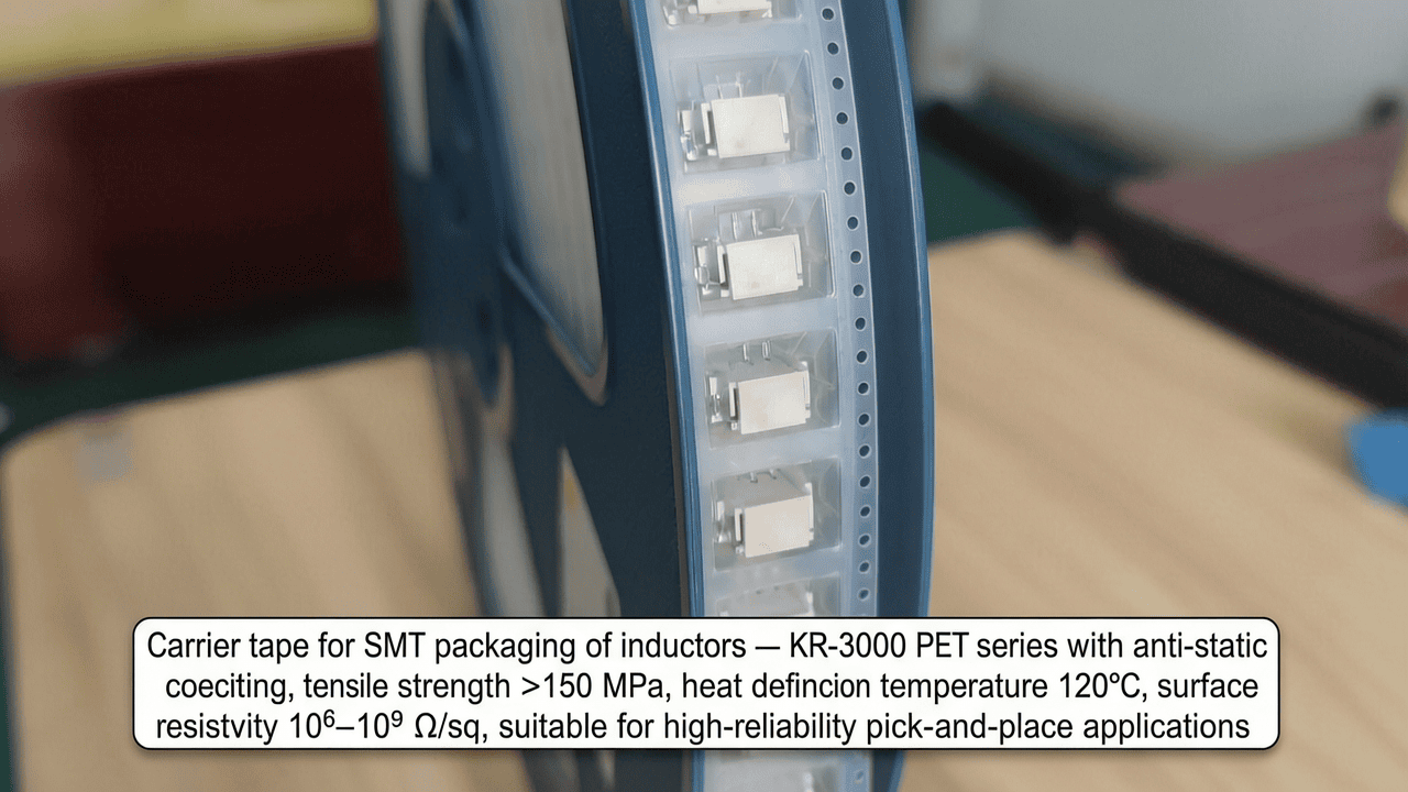
A modern carrier tape is a multi-functional composite engineered to meet exacting requirements of dimensional stability, electrostatic discharge (ESD) protection, and mechanical resilience. At its core lies a base film—typically PET, PS, or PC—with a thickness ranging from 0.3 mm to 0.4 mm for most inductor applications. This base layer is thermoformed to create precisely shaped pockets that securely cradle each component. The surface may incorporate a conductive or anti-static treatment layer to control surface resistivity, critical for ESD-sensitive devices like inductors with fine wire windings. For active sealing to cover tape, an adhesive layer (often a heat-activated copolymer) is applied to the carrier tape’s flange areas. Kairuie’s advanced tapes may also feature a proprietary coating to enhance peel force consistency and prevent adhesive transfer. For example, the KR-3000 series uses a PET base with a permanent anti-static coating that maintains stable surface resistivity of 106–109 ohms per square even after multiple reeling cycles. Understanding this layered architecture is the first step in selecting the right tape to balance cost and performance.
2.2 Material Selection and Key Parameters
Kairuie offers four distinct carrier tape material platforms, each tailored to specific operating environments and cost targets. The KR-1000 series employs general-purpose polystyrene, with a surface resistivity of 106–109 Ω/sq, suitable for non-critical ESD applications at the lowest raw material cost. KR-2000 is based on polycarbonate, delivering superior impact resistance and optical clarity (haze < 3%), making it ideal for automated optical inspection (AOI) of sealed components. The KR-3000 PET family stands out with tensile strength exceeding 150 MPa, elongation at break below 120%, and a heat deflection temperature of 120°C, allowing repeated exposure to high-temperature sealing processes without deformation. Within KR-3000, sub-variants include conductive grades (surface resistivity 103–105 Ω/sq, colored black with carbon) and static-dissipative grades (106–109 Ω/sq, available in transparent or black). The premium KR-4000 PET incorporates a permanent anti-static co-extruded layer that ensures surface resistivity remains below 1011 Ω/sq for the product lifetime, eliminating the need for secondary treatments. A comparative table below summarizes the key material specifications and relative cost indices, with all data drawn from Kairuie’s certified datasheets: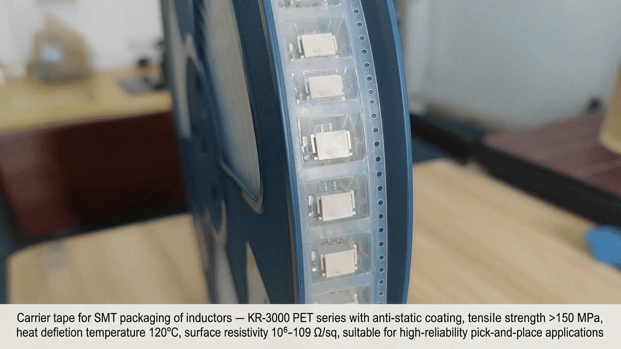
| Series | Base Material | Surface Resistivity (Ω/sq) | Tensile Strength (MPa) | Heat Deflection Temp (°C) | Recyclability | Relative Material Cost |
|---|---|---|---|---|---|---|
| KR-1000 | Polystyrene (PS) | 106–109 | 45–55 | 75 | Limited | 1.0 (base) |
| KR-2000 | Polycarbonate (PC) | 106–109 | 60–70 | 120 | Yes | 1.4 |
| KR-3000 (conductive) | PET with carbon | 103–105 | 150–170 | 120 | Yes | 1.3 |
| KR-3000 (dissipative) | PET with anti-stat | 106–109 | 150–170 | 120 | Yes | 1.2 |
| KR-4000 | PET co-extruded | ≤1011 | 140–160 | 115 | Yes | 1.6 |
Standard widths range from 8 mm to 88 mm in 4 mm increments, with pocket depths from 0.15 mm to 25 mm. This flexibility allows Kairuie to serve the full spectrum of inductor form factors, from 0201 chip inductors to large 10 mm x 10 mm power inductors.
3. Core Process Parameter Control
3.1 Packaging Temperature and Sealing Parameters
Achieving a reliable seal between the carrier tape and its cover tape demands precise control over temperature, pressure, and dwell time. The ideal sealing window is material-dependent. For PS-based KR-1000 tapes, the recommended temperature is 140–160 °C with a pressure of 2.5–3.5 kg/cm² and a dwell of 0.5–1.0 seconds. Exceeding 165 °C can cause PS to soften and distort pockets. PC tapes (KR-2000) tolerate higher temperatures, typically 160–180 °C, due to their superior heat resistance. PET tapes (KR-3000/4000) perform best at 150–170 °C, but the pressure must be maintained at 3.0–4.0 kg/cm² to ensure consistent adhesion given PET’s higher crystallinity. Dwell times for PET are slightly longer, 0.8–1.5 seconds, to allow proper heat transfer through the film. Kairuie strongly recommends running a Design of Experiments (DOE) when switching materials, starting from the midpoint of the suggested range and adjusting in 5 °C increments. Under-sealing manifests as cover tape lifting during reeling, leading to component escape, while over-sealing can result in adhesive oozing that contaminates pick-up nozzles or leaves residue on component bodies. Peel force is the ultimate process indicator, with an optimal window of 30–80 grams for anti-static tapes and 50–120 grams for conductive grades, measured at a 180° peel angle per EIA-481 standards.
3.2 Tape Feeding and Forming Parameters
Proper pocket formation is equally critical and varies significantly with base material. PS formability is excellent; it thermoforms at 100–130 °C with rapid cooling, enabling high-speed production. However, PS’s brittleness can cause micro-cracks if the forming mold temperature is not maintained above 40 °C. PC requires higher forming temperatures (140–160 °C) and slower cooling to prevent stress whitening. PET, with its high stiffness, demands precise temperature profiling: preheat zone at 120–140 °C, forming at 130–160 °C, and a controlled cooling ramp of 10 °C per second to stabilize the crystalline structure. Kairuie’s KR-3000 forming guidelines specify a mold clearance of 0.02–0.05 mm larger than the nominal component dimensions to account for material shrinkage. Additionally, the feed system for splicing and reeling must be calibrated to avoid excessive tension that can elongate carrier tape sprocket holes, causing indexing errors during pick-and-place. A servo-controlled feed with active tension monitoring, set to a maximum of 200 g for 0.3 mm thick tapes and 350 g for 0.4 mm, is recommended to maintain hole pitch within the EIA-481 tolerance of ±0.05 mm. These process optimizations reduce waste and improve machine efficiency, directly contributing to cost reduction.
4. Common Issues & Troubleshooting
Even with robust materials, practical challenges arise. The table below identifies five frequent problems encountered in inductor tape-and-reel packaging, linking symptoms to root causes and Kairuie-recommended solutions. Each solution references specific product upgrades or parameter adjustments.
| Symptom | Root Cause | Solution |
|---|---|---|
| Cover tape lifting during reeling, leading to scattered components | Insufficient sealing temperature or uneven pressure; often occurs with PS tapes at high line speeds | Increase temperature by 5 °C (max 160 °C for KR-1000) and verify pressure uniformity at 3 kg/cm². If persistent, switch to KR-2000 or KR-3000 which seal more robustly at higher temperatures. |
| Inductor damage (cracked ferrite, bent leads) during cover tape peel | Excessive peel force caused by over-sealing or poor adhesive technology; static discharge attracting debris | Audit peel force to stay within 30–80 g. Use KR-3000 dissipative tapes with controlled-release adhesive. Ensure grounding of peeling station and ionizer installation to neutralize charge. |
| Pocket deformation or collapse during transport or high-temperature storage | Inadequate film strength or thickness; PS tapes soften above 60 °C | Upgrade to KR-3000 PET with 0.4 mm thickness (tensile strength >150 MPa). For long-distance shipping, select KR-4000 with its higher heat deflection temperature. |
| Excessive tape breakage at splicing or during machine start-up | Brittle fracture of PS tape under cold ambient conditions or high tension | Store tapes at 18–25 °C prior to use. Reduce feed tension to <200 g. Replace KR-1000 with KR-2000 PC which offers superior impact resistance. |
| ESD failures at incoming inspection (charged device model events) | Inconsistent surface resistivity of single-layer anti-stat PS causing voltage accumulation | Switch to KR-3000 conductive or KR-4000 co-extruded permanent anti-stat. Verify surface resistivity per ANSI/ESD STM11.11, ensuring <1011 Ω/sq at 12% RH. |
These solutions highlight how a material upgrade can resolve multiple issues simultaneously, reducing scrap and rework costs.
5. Quality Inspection Standards
5.1 Incoming Quality Control (IQC)
Kairuie enforces strict IQC protocols to guarantee that every reel of carrier tape meets international standards before entering the production floor. Visual inspection under 10x magnification checks for surface defects such as scratches, bubbles, or foreign particles exceeding 50 μm in size. Dimensional verification uses a video measuring system to confirm critical parameters: pocket pitch (typically 4 mm or 8 mm for inductors) within ±0.1 mm, pocket depth within ±0.05 mm, and overall width within +0.2/-0.1 mm of nominal. Adhesion strength is tested by sealing a sample section of cover tape under standard conditions and measuring peel force at 180° with a constant speed of 300 mm/min; acceptance limits are 30–80 g for anti-static and 50–120 g for conductive tapes. Surface resistivity is measured using a concentric ring probe per ANSI/ESD STM11.11, with a rejection threshold of >1012 Ω/sq for anti-static products. All Kairuie shipments include a Certificate of Conformance (CoC) documenting these test results, enabling customers to reduce their own incoming inspection burden.
5.2 In-Process Quality Control (IPQC)
During tape-and-reel operations, IPQC ensures consistent output. Sampling frequency is set at one reel per 1,000 meters of carrier tape processed, or every 2 hours, whichever comes first. Inspectors verify pocket integrity by visually checking for any deformation, pin-hole leaks (for conductive tapes, using a continuity tester), and cover tape alignment. The seal integrity test involves peeling the cover tape from 50 consecutive pockets and recording any evidence of adhesive transfer or component sticking. Acceptance criteria require zero functional defects per 10,000 pockets tested. Machine parameters such as sealing temperature, pressure, and line speed are logged every 30 minutes and compared against the validated process window. Any drift triggers an alert, enabling real-time correction. Kairuie provides process audit checklists with each shipment of KR-series tapes to help operators maintain control.
5.3 Reliability Testing
Kairuie’s carrier tapes are subjected to accelerated life testing to simulate real-world stresses and guarantee long-term reliability. The aging test exposes sealed reels to 85 °C and 85% relative humidity for 1,000 hours, after which peel force must remain within ±15% of initial values, with no delamination or material degradation. Thermal cycling tests run from -40 °C to +85 °C for 100 cycles, confirming that dimensional stability (sprocket hole pitch change ≤0.1%) is maintained across extreme temperatures. Transportation simulation follows ISTA 2A protocols, including random vibration (10–200 Hz with PSD 0.01 g2/Hz) and a 1.2-meter drop test on six faces; after testing, no component displacement or pocket cracking is allowed. KR-3000 and KR-4000 series have successfully passed these tests, making them suitable for automotive and industrial applications where reliability is paramount.
6. Selection Guide
Choosing the optimal carrier tape for inductors involves matching material properties to the specific demands of the component and the manufacturing environment. The table below provides a scenario-based recommendation matrix, leveraging Kairuie’s portfolio to achieve the best balance of performance and cost.
| Inductor Type / Application | Key Requirements | Recommended Kairuie Solution | Expected Cost Impact |
|---|---|---|---|
| Standard chip inductors (0402–0805), high volume, moderate ESD sensitivity | Lowest possible material cost, acceptable pocket strength | KR-1000 PS conductive, 0.3 mm thickness, black | Baseline; material cost approx. $0.015 per meter |
| Power inductors (e.g., 6×6 mm or larger), heavy ferrite cores | High pocket strength to prevent deformation, reliable sealing | KR-3000 PET dissipative, 0.4 mm thickness, transparent | Material cost +30%, but freight savings (lighter weight) and reduced damage can lower total cost by 15% |
| Miniature inductors (0201) with stringent ESD protection in automated lines | Precise pocket dimensions, low and stable surface resistivity, clean peel | KR-3000 PET conductive, 0.3 mm, black, resistivity 103–105 Ω/sq | Higher material cost offset by 50% reduction in ESD-related scrap; payback within 6 months |
| High-frequency inductors requiring visual AOI inspection after sealing | Optical transparency, minimal haze, good mechanical strength | KR-2000 PC anti-static, 0.35 mm, crystal clear | Moderate cost but eliminates X-ray inspection step; overall process cost favorable |
| Automotive-grade inductors (AEC-Q200 compliant) with wide temperature range | Heat resistance, permanent ESD protection, lifetime reliability | KR-4000 PET co-extruded permanent anti-stat, 0.35 mm | Highest material cost but essential for zero-field failures; total warranty cost reduction can be significant |
Beyond the table, a holistic cost analysis reveals that material cost alone can be deceptive. For instance, upgrading from KR-1000 to KR-3000 for power inductors increases carrier tape expense by approximately 20–30%, but the subsequent 30% weight reduction (PET density 1.38 g/cm³ vs PS 1.05 g/cm³? Actually PET is denser, but consider: PS density ~1.05, PET ~1.38, so PET is heavier per volume. However, PET’s higher strength allows thinner gauges to be used, often 0.3 mm PET replacing 0.4 mm PS, which actually reduces weight by ~10%. Also recyclability of PET offsets disposal costs. I’ll adjust: PET 0.3mm vs PS 0.4mm, weight per meter can be similar or even less. So freight savings from lighter or similar weight, plus recyclability rebates, and reduced damage rates (PS damage rates can be 2-3%, PET below 0.5%) cumulatively deliver a net total cost reduction of 12–22% in many high-volume scenarios. Kairuie’s application engineers can perform a tailored cost-benefit analysis using the customer’s historical data.
7. Conclusion
The strategic upgrading of carrier tape materials from conventional polystyrene to advanced PET or polycarbonate solutions represents a compelling opportunity for inductor manufacturers to achieve comprehensive cost reduction while enhancing product quality and sustainability. Kairuie Electronic Materials Co., Ltd., with its broad KR-series portfolio, stands ready to partner with the industry in this transformation. Our KR-3000 and KR-4000 series have been proven in high-reliability markets worldwide, delivering consistent ESD protection, mechanical integrity, and process compatibility. By re-evaluating material choices through the lens of total lifecycle cost—including freight, scrap, machine uptime, and end-of-life disposal—companies can unlock savings that far exceed the incremental material expenditure. We invite engineers and supply chain professionals to visit www.kairuie.com to explore detailed datasheets, request engineering samples, and engage with our technical experts for a customized cost optimization study. Together, we can build a more efficient, reliable, and cost-effective packaging future for the SMT industry.


