凯瑞尔电子材料
1. Introduction
In the rapidly evolving landscape of consumer electronics, MEMS (Micro-Electro-Mechanical Systems) microphones have become a cornerstone component, enabling voice interfaces in smartphones, wearables, and smart home devices. The assembly of these delicate components demands both high speed and extreme precision, often with packaging tolerances as tight as ±0.05 mm. Two of the most persistent challenges in high-speed MEMS microphone pick-and-place are “throw material” (component ejection errors) and “abnormal noise” (acoustic anomalies caused by mechanical stress). These issues not only increase production costs through rework and scrap but also compromise the acoustic integrity of the final product. The root causes often lie in the performance of electronic packaging materials—adhesives, underfills, and die attach films—which must balance adhesion strength, dispensing accuracy, and stress relief. This article explores how Kairuie Electronic Materials Co., Ltd.’s advanced material solutions, including the KA‑1000 conductive adhesive, KUF‑500 capillary underfill, and KDAF‑080 die attach film, address these challenges by providing precise bond line control, optimized curing profiles, and robust thermal‑mechanical properties. Through detailed process parameter control, systematic troubleshooting, and rigorous quality standards, manufacturers can achieve zero‑defect assembly and superior acoustic performance.
2. Product Structure & Material Composition
2.1 Kairuie KA‑1000 Series Conductive Adhesive
The KA‑1000 series is a silver‑filled epoxy adhesive designed for the die bonding of MEMS microphone sensors to substrates. It features a three‑layer structure: a PET release liner (50 μm thickness), a precisely metered adhesive layer (25 μm ±2 μm), and a protective top film to prevent contamination during handling. The adhesive layer exhibits a surface resistivity of ≤5×10⁻⁴ Ω·cm, ensuring excellent electrical conductivity for grounding and signal integrity. Its glass transition temperature (Tg) is 145 °C (by DMA), providing high thermal stability during reflow soldering and device operation. With a coefficient of thermal expansion (CTE) of 28 ppm/°C below Tg and 85 ppm/°C above Tg, the KA‑1000 minimises stress on the MEMS diaphragm, reducing the risk of abnormal noise due to micro‑cracks or warpage. The adhesive’s thixotropic index of 2.8 allows for precise dot dispensing without slump, critical for maintaining the 0.05 mm positional tolerance during die placement.
2.2 Kairuie KUF‑500 Capillary Underfill
The KUF‑500 is a low‑viscosity (450 mPa·s at 25 °C) epoxy underfill specifically formulated for flip‑chip MEMS microphone packages. It flows rapidly into the 15–30 μm gap between the chip and substrate by capillary action, then cures to form a stress‑reducing layer. Its filler content of 55 wt% silica particles (average particle size 0.3 μm) controls CTE to 22 ppm/°C, matching that of the silicon die and BT resin substrate. The material is supplied in a pre‑mixed frozen syringe configuration, with a pot life of 16 hours at 25 °C and a shelf life of 12 months at –40 °C. The underfill’s adhesion strength exceeds 45 MPa (die shear test on bare silicon), effectively preventing die shift during high‑speed handling and subsequent acoustic vibration.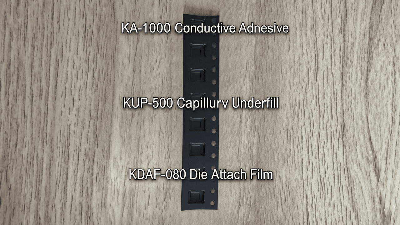
2.3 Kairuie KDAF‑080 Die Attach Film
For ultra‑thin MEMS microphone packages (total thickness ≤0.3 mm), the KDAF‑080 die attach film offers a non‑conductive alternative with a total thickness of 80 μm (±2 μm). It consists of a 38 μm PET carrier, a 38 μm adhesive layer, and a 4‑μm antistatic coating that reduces surface resistivity to 1×10⁶–1×10⁸ Ω/sq, mitigating ESD risks during die singulation and placement. The adhesive, based on a modified acrylic chemistry, provides a die shear strength of 12 MPa at room temperature and retains 80 % of that strength after 1000 hours of 85 °C/85 % RH ageing, per JEDEC JESD22‑A101. This film’s precise thickness uniformity (total thickness variation ≤2 μm) enables consistent bond line control, which is essential for avoiding tilt‑induced throw material errors in high‑speed mounters.
3. Core Process Parameter Control
3.1 Dispensing and Printing Parameters
For KA‑1000 adhesive dispensing, the recommended needle gauge is 25G (ID 260 μm) at a stand‑off height of 100 μm. The dispensing pressure should be set to 0.25–0.35 MPa with a pulse time of 15–20 ms, yielding a dot diameter of 300±25 μm. Maintaining a temperature of 23±2 °C in the dispensing area ensures consistent viscosity and tail break. For stencil printing of KDAF‑080 film, a metal stencil with a thickness of 100 μm and aperture size of 200×200 μm are employed, with a squeegee pressure of 0.5–0.7 kg/cm² and print speed of 25–50 mm/s. Snap‑off distance is critical: 0.1–0.2 mm minimises stringing and void formation.
3.2 Placement Accuracy and Force Control
During high‑speed pick‑and‑place, the placement force must be tightly managed to prevent die damage and adhesive squeeze‑out. For MEMS microphones using KA‑1000, the recommended placement force is 2.0–3.0 N, with a placement speed of 0.5–1.0 seconds per component. The placement accuracy required is ±25 μm (3σ) to meet the 0.05 mm overall tolerance stack. Real‑time vision alignment systems verify X, Y, and theta offsets, and the machine must be capable of dynamic correction based on adhesive dot location. For KUF‑500 underfill, pre‑heating the substrate to 80 °C for 10 seconds prior to placement reduces the adhesive viscosity by 30 %, promoting faster wetting and reducing void risk.
3.3 Cure Profile Optimisation
The cure schedule profoundly influences material properties and acoustic performance. KA‑1000 adhesive is typically cured at 120 °C for 30 minutes, or in a step profile: ramp from 25 °C to 120 °C at 3 °C/min, hold for 20 minutes, then cool at 2 °C/min. Fast ramps (>5 °C/min) induce internal stresses that can deform the MEMS membrane, leading to abnormal noise. KUF‑500 underfill cures at 150 °C for 60 minutes; an oven with ±2 °C uniformity is required to avoid incomplete cross‑linking in corner dies. KDAF‑080 film is laminated at 60 °C with 0.2 MPa pressure for 30 seconds, then bonded with a post‑cure bump at 100 °C for 10 minutes to achieve full adhesion. For all materials, a nitrogen atmosphere (O₂ <50 ppm) prevents oxidation of silver fillers.
4. Common Issues & Troubleshooting
| Symptom | Root Cause | Solution |
|---|---|---|
| Throw material (die falls off nozzle or misplacement) | Adhesive tack insufficient; pick‑up force too high; PET liner residue on die backside | Increase dispensing temperature to 25 °C; reduce pick‑up acceleration; inspect PET release liner quality with AFM; switch to KDAF‑080 with antistatic coating |
| Abnormal noise (acoustic distortion/high noise floor) | Die tilt >0.1° due to uneven adhesive thickness; CTE mismatch stress on diaphragm | Tighten placement force tolerance to ±0.2 N; verify adhesive dot diameter consistency (±10 μm); use KUF‑500 underfill to balance CTE; inspect diaphragm flatness post‑cure |
| Voiding in adhesive layer (>2% void area) | Entrapped air during dispensing or placement; outgassing from substrate or adhesive | Optimise dispensing path (spiral pattern); pre‑bake substrate at 120 °C for 2 h; use vacuum placement environment; select KA‑1000 with low volatile content (<0.1 %) |
| Adhesive bleed/overflow onto bond pads | Excessive placement force; adhesive viscosity too low; placement offset | Reduce placement force to 2.0 N; verify adhesive thixotropic index >2.5; improve vision alignment; consider KDAF‑080 film for no‑flow applications |
| Delamination after TC or HAST | Poor adhesion to substrate surface; moisture absorption | Enhance substrate plasma treatment; apply KUF‑500 with silane coupling agent; ensure proper cure degree (DSC verification); use KA‑1000 with 85 °C/85% RH rating |
5. Quality Inspection Standards
5.1 Incoming Quality Control (IQC)
All Kairuie materials undergo rigorous IQC. For KA‑1000, each lot is inspected for visual appearance (no gels, colour change), viscosity (Brookfield CP51, 10 rpm), and thixotropic index. The PET liner thickness is checked at 5 points across the width using a laser micrometer; deviation >±2 μm triggers rejection. Peel strength (180° peel at 300 mm/min) on Al₂O₃ ceramic must exceed 12 N/cm. KDAF‑080 film is inspected for total thickness, surface resistivity, and die shear strength on mock die. KUF‑500 is tested for flow time (time to fill a 20 μm gap capillary) and ionic purity (Na⁺, Cl⁻ <10 ppm).
5.2 In‑Process Quality Control (IPQC)
During assembly, critical parameters are monitored at intervals determined by process capability (Cpk ≥1.67). Dispensing dot diameter is sampled every 2 hours with an automated vision system; limits are set at nominal ±15 μm. Placement force is verified every 4 hours using a load cell. For underfill, the fillet height is inspected post‑flow on 5 samples per tray, with acceptance criterion of 30–50 % of die height. Void inspection via X‑ray is performed on 1 board per shift, with void rate <2 % deemed acceptable. Reflow profile charts are reviewed daily.
5.3 Reliability Testing
Reliability qualification follows JEDEC and customer‑specific standards. Temperature cycling (TC) from –65 °C to +150 °C for 1000 cycles (JESD22‑A104) must show no delamination or electrical failure. High‑temperature storage (HTS) at 150 °C for 1000 hours ensures long‑term thermal stability. Biased HAST (130 °C, 85 % RH, 33.3 V) is run for 96 hours to check for electrochemical migration. For acoustic reliability, finished MEMS microphones are subjected to transport simulation: sinusoidal vibration 10–500 Hz, 0.5 g²/Hz, 2 hours per axis, followed by acoustic testing to confirm noise floor change <1 dB. All Kairuie materials have been validated to withstand these test regimes when processed within the specified windows.
6. Selection Guide
Selecting the right material for MEMS microphone assembly depends on package type, die size, substrate material, and throughput requirements. The table below provides a quick reference for matching Kairuie products to common application scenarios.
| Application Scenario | Recommended Kairuie Product | Key Advantages |
|---|---|---|
| Low‑cost, high‑volume smartphone mics (die size ≤1 mm², BT substrate) | KA‑1000 conductive adhesive | Fast dispensing, high Tg, excellent electrical conductivity, proven throw material reduction through tuned thixotropy |
| Flip‑chip, wafer‑level package mics (gap <30 μm, fine‑pitch bumps) | KUF‑500 capillary underfill | Ultra‑low CTE, fast flow, minimal bleed, eliminates die shift and stress‑induced noise |
| Ultra‑thin, bottom‑port mics (total height <0.4 mm, flexible PCB) | KDAF‑080 die attach film | Precise thickness (<2 μm variation), ESD protection, no adhesive overflow, ideal for automatic film lamination |
| High‑reliability automotive/aerospace mics (wide temperature range, long life) | KA‑1000 + KUF‑500 (dual‑material process) | Combination ensures mechanical robustness from –55 to 150 °C; proven 3000‑cycle TC and 2000‑hour HTS |
For applications demanding even tighter tolerances (<±0.03 mm), Kairuie offers customised versions with modified rheology and filler counts. Our application engineering team can conduct joint trials to fine‑tune material and process parameters for your specific equipment set.
7. Conclusion
The MEMS microphone market demands packaging solutions that deliver zero‑defect assembly at ever‑increasing speeds while maintaining pristine acoustic quality. Kairuie Electronic Materials Co., Ltd.’s KA‑1000, KUF‑500, and KDAF‑080 materials directly address the root causes of throw material and abnormal noise through precise bond line control, optimised thermal‑mechanical properties, and high‑purity formulations. By integrating these materials with rigorous process controls and quality inspection protocols, manufacturers can achieve placement accuracies within 0.05 mm, void rates below 2 %, and stress‑free die attach that preserves microphone sensitivity. As a leader in SMT electronic packaging materials, Kairuie is committed to continuous innovation and customer collaboration. We invite industry peers to explore our full product portfolio and share insights on best practices. Visit us at www.kairuie.com to learn more or to schedule a technical consultation.


