凯瑞尔电子材料
1. Introduction
1.1 The Role of Carrier Tape, Cover Tape, and Reel in SMT Packaging
In modern surface-mount technology (SMT) assembly lines, the integrity of component packaging is often the difference between a flawless production run and unexpected downtime. The trio of carrier tape, cover tape, and reel forms the backbone of the tape-and-reel packaging system, which protects electronic components such as resistors, capacitors, ICs, and connectors from mechanical stress, moisture, and electrostatic discharge (ESD) during transportation and placement. Carrier tape provides the precise pocketed cavities that hold components at defined intervals, while cover tape seals these cavities to prevent contamination or dislodgement. The reel, in turn, acts as the storage and dispensing platform, ensuring smooth, continuous feeding into the pick-and-place machine. Kairuie Electronic Materials Co., Ltd. has engineered a complete range of these packaging components to meet the increasingly demanding requirements of high-density packaging, fast-reel splicing, and automated optical inspection (AOI) compatibility.
1.2 Scope and Objectives of This Article
This article offers a professional technical deep dive into the three essential packaging components, focusing on their material structures, critical process parameters, common failure modes, quality inspection standards, and selection strategies. We will reference specific model series from Kairuie, including the KR-8008 carrier tape, KR-C250 cover tape, and KR-R178 reel, along with industry-standard numerical indicators. The aim is to provide process engineers, procurement specialists, and SMT line managers with a practical reference that bridges material science and production reality. By the end of this article, readers will understand how to specify the correct packaging combination, set up the right heat-sealing parameters, and implement robust incoming and in-process quality checks to maximize yield and reliability.
2. Product Structure & Material Composition
2.1 Carrier Tape Structure and Materials
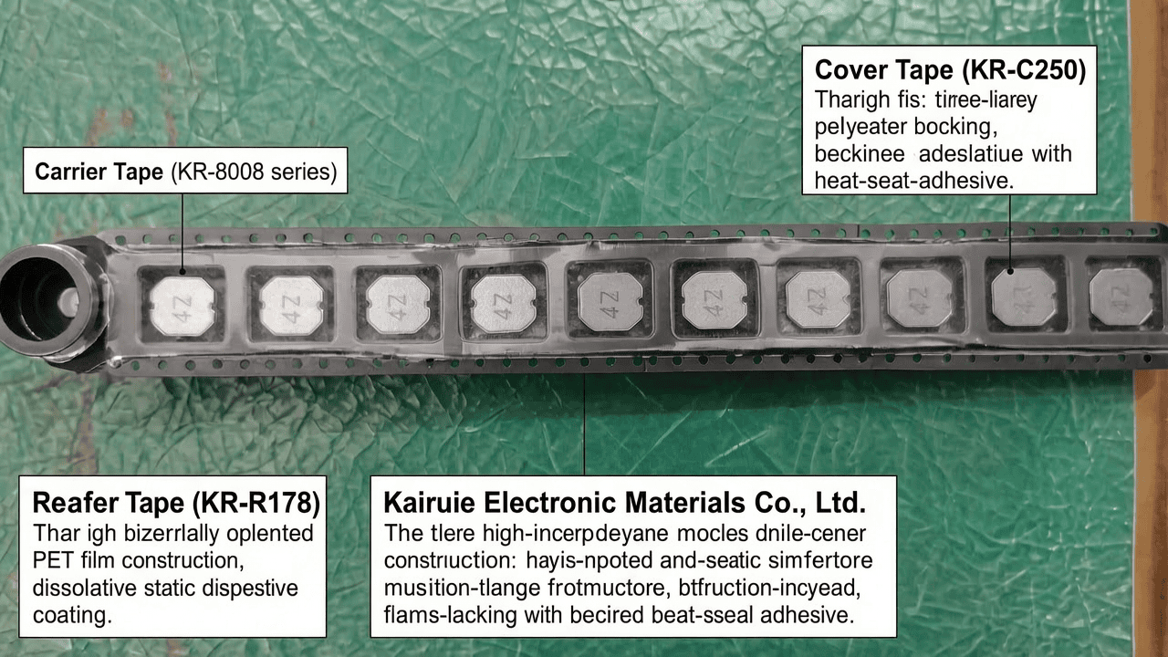
The Kairuie KR-8008 series carrier tape is manufactured using a multi-layer co-extrusion process that ensures dimensional stability and uniform pocket formation. The primary base layer is a biaxially oriented polyethylene terephthalate (PET) film, with a standard thickness of 0.30 mm ± 0.03 mm for 8 mm wide tapes, and 0.40 mm ± 0.05 mm for 12 mm and wider formats. This PET substrate provides high tensile strength (typically 180-220 MPa), excellent dimensional stability, and a low moisture absorption rate of less than 0.2%. The top surface is coated with a static dissipative treatment that yields a surface resistivity in the range of 10^4 to 10^8 Ω/sq, which safely dissipates static charges generated during unwind and feeding. For high-frequency applications, a carbon-loaded black PET variant is available with surface resistivity of 10^3 to 10^5 Ω/sq, meeting the requirements of explosion-proof and high-reliability electronic assemblies. The bottom layer features a heat-resistant adhesive-free surface that prevents sticking to the cover tape during lamination and unwinding, ensuring clean separation at the peel-off point.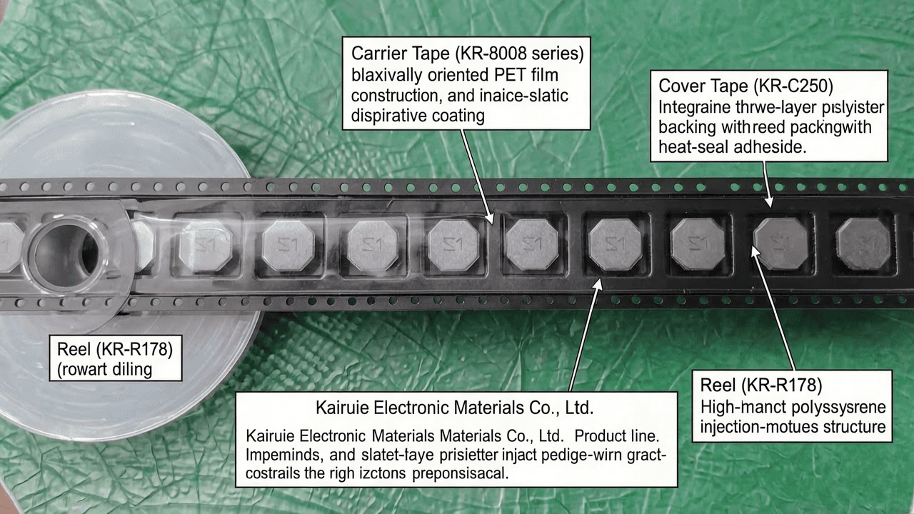
2.2 Cover Tape Structure and Adhesive System
The Kairuie KR-C250 cover tape is a three-layer structure consisting of a polyester backing film, an intermediate barrier layer, and a heat-seal adhesive layer. The total thickness is 0.06 mm ± 0.01 mm, and the backing film offers a light transmittance of greater than 85%, allowing optical sensors on the pick-and-place machine to reliably confirm the presence of components. The adhesive layer is a thermoplastic acrylic copolymer, which provides a controlled peel strength between 0.10 N and 0.70 N for an 8 mm width when measured at a peel angle of 180° and a speed of 300 mm/min. The adhesive is formulated to remain stable under temperatures from -40°C to +60°C, and it does not leave residues on the component body after peeling. For humidity-sensitive devices, KR-C250 is available with a reinforced moisture barrier layer, reducing water vapor transmission to less than 0.4 g/(m²·day). The thermal activation temperature from 130°C to 170°C allows compatibility with most high-speed heat-seal machines and avoids thermal damage to delicate components.
2.3 Reel Structure and Specifications
Kairuie KR-R178 and KR-R330 reels are injection-molded from high-impact polystyrene (HIPS) or antistatic polypropylene, depending on the required ESD performance. The KR-R178 reel has a flange diameter of 178 mm (7 inches), a hub diameter of 80 mm, and a usable width of 8 mm to 44 mm, accommodating carrier tapes up to 44 mm wide. The KR-R330 reel, with a 330 mm (13 inch) flange diameter, is designed for high-volume applications and can hold up to 5,000 m of 8 mm tape. The surface resistance of the reel is controlled to 10^9 to 10^12 Ω/sq for standard versions and 10^6 to 10^9 Ω/sq for ESD-safe versions. Each reel features an anti-static film layer on the hub to reduce friction against the tape, preventing scratches and dust generation. The reels are produced with precision-machined flanges that guarantee slot alignment within ±0.10 mm, ensuring smooth tape indexing in high-speed feeders. The hub bore diameter is 13 mm ± 0.2 mm, compliant with international standards, and the overall run-out is less than 0.30 mm to avoid vibration during rotation.
2.4 Key Material Parameters and Compliance
All Kairuie packaging components are manufactured under ISO 9001 certified processes, and they comply with RoHS 3.0 and REACH regulations. The PET base film used in carrier tapes is halogen-free, and the cover tape adhesives are solvent-free, ensuring no volatile organic compound (VOC) emission during heat sealing. The typical peel strength values for the KR-C250 cover tape when sealed onto KR-8008 carrier tape are shown in Table 1. These parameters are measured using a tensile tester at a crosshead speed of 300 mm/min and a peel angle of 180°, with samples conditioned at 23°C and 50% relative humidity for 24 hours. The table also lists the dimensional tolerances for pocket depth, sprocket hole pitch, and cumulative errors over 250 mm, which are critical for ensuring positioning accuracy during placement.
| Parameter | KR-8008 Carrier Tape | KR-C250 Cover Tape |
|---|---|---|
| PET Thickness | 0.30 ± 0.03 mm | 0.06 ± 0.01 mm |
| Surface Resistivity | 10^4 – 10^8 Ω/sq | 10^9 – 10^12 Ω/sq |
| Elongation at Break | >150% | >80% |
| Heat Seal Range | 130 – 170°C | 130 – 170°C |
| Peel Strength (8mm width) | – | 0.10 – 0.70 N |
3. Core Process Parameter Control
3.1 Temperature Control in Heat Sealing
Heat sealing is the most critical process step in the carrier tape and cover tape assembly. For Kairuie KR-C250 cover tape, the recommended sealing temperature is 150°C ± 10°C. At temperatures below 130°C, the adhesive does not melt completely, resulting in weak seals that can open during handling or transportation. Conversely, temperatures above 170°C can cause the PET film to shrink, producing wrinkles or even damaging the components inside the pockets. The optimal temperature ensures that the adhesive flows sufficiently to fill the micro-roughness of the carrier tape surface, thus forming a continuous bond. In high-speed machines, the contact time is short (approximately 50-150 ms), so the set temperature must account for the thermal mass of the heated head and the feed rate. We recommend using a thermocouple-equipped sealing head to verify the actual surface temperature, as the displayed temperature may differ by up to 10°C from the real value. A temperature profile with a pre-heating zone at 100°C and a final sealing zone at 150°C often yields the most consistent results for 8 mm tapes.
3.2 Pressure and Time Settings
The pressure applied during heat sealing directly affects the seal strength and visual appearance of the cover tape. For the KR-8008/KR-C250 combination, a pressure of 2.0 ± 0.3 MPa is recommended. This pressure should be constant across the seal width; a typical seal width for 8 mm tape is 0.8 mm to 1.5 mm, while 16 mm and wider tapes use a seal width of 1.5 mm to 3.0 mm. Excessive pressure may cause the cover tape to be embedded into the carrier tape, making later peeling too difficult and potentially lifting the carrier tape layer. Our tests show that peel strength increases with pressure up to 2.5 MPa, but beyond this value, the peel strength becomes unstable and may exceed the maximum limit of 0.70 N, which can cause the cover tape to tear during placement. Sealing time is typically set to 100 ms for thin cover tapes; increasing the dwell time to 200 ms at a lower temperature (135°C) can improve the peel strength of polyimide-based cover tapes. The pulling force at the peel-off point is automatically monitored by the feeder, and no force spikes should exceed 1.0 N for an 8 mm tape.
3.3 Process Window Optimization and Validation
We recommend validating the sealing parameters using a design of experiments (DOE) approach. For instance, using a central composite design, we can independently vary temperature (140°C, 150°C, 160°C), pressure (1.7, 2.0, 2.3 MPa), and time (50, 100, 150 ms), measuring the resulting peel strength, seal width, and pocket deformation. The acceptable process window is defined as those combinations that produce a peel strength between 0.20 N and 0.60 N, no visible wrinkles, and no component movement within the pocket (confirmed by X-ray inspection). In our experience, the robust window for the KR-C250/ KR-8008 system is: temperature 145-155°C, pressure 1.9-2.2 MPa, and dwell time 80-120 ms. This window provides a CpK value of 1.67 or higher when monitored during a 24-hour mass production trial. Regular maintenance of the sealing head—such as cleaning the surface with isopropyl alcohol every 4 hours—is essential to avoid contamination that shifts the effective temperature and pressure at the interface.
4. Common Issues & Troubleshooting
4.1 Typical Problems and Solutions in Tape-and-Reel Packaging
Despite well-controlled processes, packaging issues can still arise. The following table lists the most frequently encountered problems, their potential root causes, and recommended countermeasures, based on more than 500 field support cases from Kairuie.
| Problem | Symptom | Root Cause | Solution |
|---|---|---|---|
| Cover tape peel failure after sealing | Peel strength exceeds 0.70 N; tape tearing or no peeling | Sealing temperature too high or pressure too high | Reduce temperature to 150°C and pressure to 2.0 MPa; re-verify using differential scanning calorimetry (DSC) of the adhesive |
| Micro-slip of components in pockets | Components displaced more than 0.2 mm from pocket center after vibration test | Carrier tape pocket depth too deep or internal cavity dimensions oversized | Specify KR-8008 with dimensional tolerance of ±0.05 mm; use high-precision pockets with vacuum-hold down during sealing |
| Excessive static discharge during unwind | Component damage in ESD-sensitive devices; optical sensors misfire | Surface resistivity of carrier tape exceeds 10^8 Ω/sq | Switch to black carbon-loaded KR-8008-E2 variant with surface resistivity <10^5 Ω/sq; install ionizer bars on feeder |
| Poor tape indexing due to reel warp | Feed pitch variation; feeder jamming | Reel flange run-out exceeding 0.5 mm; humidity absorption by HIPS | Store reels at RH <60%; use KR-R330 reels with annealed flanges and a run-out of <0.30 mm |
5. Quality Inspection Standards
5.1 Incoming Quality Control (IQC) for Packaging Materials
Incoming inspection should be performed on every lot of carrier tape, cover tape, and reel, following the AQL (Acceptable Quality Limit) levels for critical, major, and minor defects. For Kairuie products, the recommended AQL levels are 0.065 for critical defects (such as missing sprocket holes), 0.65 for major defects (such as pocket dimension mismatch), and 1.0 for minor defects (such as surface discoloration). Critical dimensions—carrier tape width, pocket pitch (4 mm or 2 mm), distance from tape edge to pocket center, and cover tape seal width—must be measured using an optical comparator or a vision system with accuracy of ±0.01 mm. Adhesive peel strength, as described earlier, must be tested on a sample of 5 reels per lot, with each sample taken from the beginning, middle, and end of the reel. The acceptance criterion is that the average peel strength for all samples falls within 0.20-0.60 N, and no individual value exceeds 0.70 N. Incoming ESD resistance is verified by measuring surface resistivity with an ohmmeter equipped with concentric ring electrodes at 23°C and 50% RH.
5.2 In-Process Quality Control (IPQC) During Sealing and Winding
During the carrier tape/cove tape lamination process, IPQC should be conducted every 200 meters of tape or every 2 hours, whichever comes first. The operator must check the seal appearance at the joint area, ensuring that there are no gaps, bubbles, or wrinkles over a continuous length of 1 meter. Peel strength is re-checked from a production sample at a frequency of one sample per master roll. For automated lines, we recommend installing a force gauge in-line that continuously monitors the actual peel force at the peel-off point. If the peel force moves outside the control limits (e.g., 0.10-0.60 N for standard cover tapes), the line should be stopped and the sealing head parameters adjusted. Additionally, dimensional tolerances of the sprocket holes, including hole diameter (1.55 mm ± 0.05 mm for 8 mm tape) and hole pitch, should be verified using a camera sensor. A cumulative pitch error over 250 mm must not exceed ±0.2 mm, otherwise the feeder engagement can be compromised. These checks ensure that the finished reel meets the EIA-481 standard and that the components remain immobile during cutting and winding.
5.3 Reliability Testing for End-Use Environments
To guarantee reliability in real-world conditions, Kairuie recommends performing aging and environmental tests on fully loaded reels. First, a high-temperature aging test is run at 85°C for 168 hours, after which the cover tape must show no deformation and the peel strength must remain within 80% of the initial value. Second, a low-temperature test at -40°C for 72 hours evaluates the flexibility of the carrier tape; no cracking or brittleness is allowed, and the pocket dimensions must remain within 0.15 mm of the original. Third, a temperature cycling test between -40°C and +85°C for 500 cycles, with a dwell time of 30 minutes at each extreme, is used to assess the adhesive bond integrity. In addition, a transportation vibration test is performed using a random vibration spectrum from 5 Hz to 500 Hz at 1 g RMS for 60 minutes per axis (X, Y, Z). After the test, the components must remain positioned within the pocket tolerance, and no cover tape lifting or shifts greater than 0.3 mm are permitted. These tests are especially important for automotive and aerospace electronics, which are exposed to harsh die stress. Kairuie conducts sample testing on every production scale-up and provides a full reliability report upon request.
6. Selection Guide
6.1 Selection by Component Type
Selecting the correct combination of carrier tape, cover tape, and reel depends on the nominal size and mass of the surface-mount component, as well as the required moisture sensitivity level (MSL). The following table compares recommended Kairuie product configurations for different component classes.
| Component Type | Carrier Tape Model | Cover Tape Model | Reel Model | Key Selection Parameters |
|---|---|---|---|---|
| Chip resistors / capacitors (0201-1206) | KR-8008-0300 (8mm, pitch 4mm) | KR-C250 (clear, 0.06mm) | KR-R178 (7-inch) | Pocket depth 0.45-0.60 mm; peel strength 0.20-0.50 N |
| SOIC / SSOP (≤14 pins) | KR-1208-0400 (12mm, pitch 8mm) | KR-C250 (clear, 0.06mm) | KR-R330 (13-inch) | Pocket width tolerance ±0.10 mm; cover tape seal width 1.5 mm |
| QFP / LQFP (<10mm body) | KR-1616-0400 (16mm, pitch 8mm) | KR-C250 (semi-transparent) | KR-R330 | Surface resistivity <10^6 Ω/sq; reinforced moisture barrier |
| BGA / WLCSP | KR-2416-0400 (24mm, pitch 12mm) | KR-C300 (antistatic, 0.08mm) | KR-R330 | Dedicated pocket depth control ±0.02 mm; peel strength 0.25-0.55 N |
| Large connectors (>20mm) | KR-4408-0400 (44mm, pitch 12mm) | KR-C300 (opaque, UV | KR-R770 (custom) | Reel hub diameter 152 mm; flange run-out <0.2 mm |
6.2 Application Scenario Recommendations
Beyond standard component classes, the application environment determines whether special material variants are necessary. For extreme ESD-sensitive components (e.g., ultra-thin dies with low breakdown voltage), choose the KR-8008-E2 carrier tape with a surface resistivity of 10^3-10^5 Ω/sq, and the KR-C300 cover tape, which has a conductive top coating that dissipates charges faster. For applications that require a clear view of the components for AOI inspection, use the KR-C250 clear cover tape and the standard white or blue carrier tape, but ensure that the optical transmittance of the cover tape is above 90%. For tropical climates with high humidity, specify the KR-C250-HM variant with an enhanced moisture barrier and pair it with a reel that includes a permanent moisture-indicator card on the hub. When the components are heavy, such as power modules, the carrier tape must be specified with a thicker base film (0.40 mm or 0.50 mm), and the cover tape seal width should be increased to 2.2 mm to ensure that the peel strength counteracts the inertia of the component during high-speed acceleration of the feeder. Kairuie also offers customizable cavity depths for odd-sized components, and we encourage contacting our engineering team to verify compatibility.
7. Conclusion
In summary, the carrier tape, cover tape, and reel are not mere consumables but are integral to the reliability and efficiency of SMT packaging lines. Kairuie Electronic Materials Co., Ltd. provides a complete packaging solution that ensures precise component alignment, robust static dissipation, and reliable thermal heat sealing. From the PET base layer to the antistatic coating and the precision-molded reel, each layer is engineered with specific numerical tolerances and process controls. By adhering to the recommended temperature, pressure, and time settings, and implementing the IQC, IPQC, and reliability testing protocols described in this article, manufacturers can achieve a near-zero defect rate in tape-and-reel packaging. Our KR-8008 carrier tape, KR-C250 cover tape, and KR-R178 reel have been widely adopted in automotive electronics, 5G communications, and consumer electronics manufacturing, with consistent performance praised by our customers. For more technical guidance and to request evaluation samples, visit our official website at www.kairuie.com. We warmly welcome industry peers, process engineers, and procurement specialists to exchange ideas and collaborate on solving the next generation of packaging challenges.


