凯瑞尔电子材料
1. Introduction
In the realm of surface mount technology (SMT), carrier tape plays a pivotal role in the reliable delivery of miniature components to placement machines. For MEMS silicon microphones (MEMS SiMic) and electret condenser microphones (ECM), the demand for precision has escalated due to their shrinking sizes and high-speed assembly requirements. Tombstoning, reverse placement, and pick-up failures are common defects that directly impact yield and cost. This article delves into the critical aspects of high-precision micro carrier tape, focusing on product structure, process control, quality assurance, and selection guidelines—all underpinned by real-world parameters and best practices.
2. Product Structure & Material Composition
2.1 Layer Structure
A typical high-precision carrier tape consists of three functional layers: a base layer (carrier body), an adhesive layer (cover tape bonding), and a release treatment layer (optional). The base layer is usually made of PET (polyethylene terephthalate) with a thickness ranging from 0.25 mm to 0.45 mm, offering dimensional stability and rigidity. The adhesive layer is tailored to provide a controlled peel strength (typically 0.2–1.0 N/cm) to prevent accidental detachment during handling. For MEMS microphones, a conductive adhesive may be used to dissipate electrostatic discharge (ESD), with surface resistivity below 10^6 Ω/sq.
2.2 Key Parameters
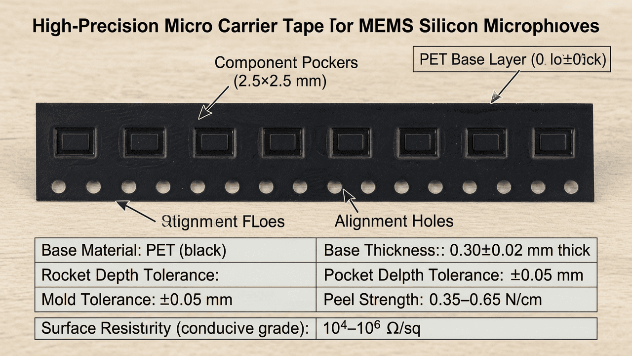
The mold precision for our micro carrier tape is controlled within ±0.05 mm, which is essential for tiny components like MEMS die sizes of 2.5×2.5 mm. The pocket depth tolerance is ±0.03 mm, ensuring consistent component seating. The cover tape width is typically 5–20 mm, with a sealing temperature range of 130–180°C. Below is a reference table of typical specifications: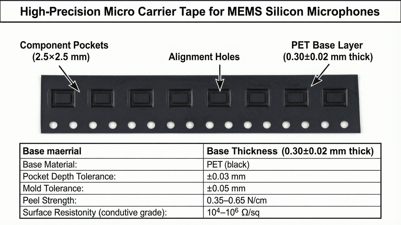
| Parameter | Specification | Unit |
|---|---|---|
| Base Material | PET (black/transparent) | – |
| Base Thickness | 0.30±0.02 | mm |
| Pocket Depth Tolerance | ±0.03 | mm |
| Mold Tolerance | ±0.05 | mm |
| Peel Strength (cover tape) | 0.35–0.65 | N/cm |
| Surface Resistivity (conductive grade) | 10^4–10^6 | Ω/sq |
3. Core Process Parameter Control
3.1 Temperature
During cover tape sealing, the temperature must be carefully controlled to avoid damaging the tape or weakening the peel strength. Recommended sealing temperature is 150±5°C for standard PET tapes. Too low a temperature (<130°C) results in weak adhesion; too high (>180°C) may cause tape shrinkage or deformation.
3.2 Pressure
Sealing pressure should be set between 2.0–4.0 kg/cm², depending on the tape width and machine type. Insufficient pressure leads to uneven sealing, while excessive pressure can crush delicate component cavities.
3.3 Time
The dwell time (sealing time) is typically 0.3–0.8 seconds. For high-speed production, a balance must be struck to ensure full heat transfer without causing thermal stress. Optimal process window: Temp 145–155°C, Pressure 2.5–3.5 kg/cm², Time 0.4–0.6 sec.
4. Common Issues & Troubleshooting
| Symptom | Root Cause | Solution |
|---|---|---|
| Component tombstoning | Pocket depth mismatch or tape warpage | Verify pocket depth tolerance within ±0.03 mm; ensure tape flatness |
| Reverse placement (flipped component) | Insufficient pocket clearance or static charge | Increase pocket width by 0.1 mm; use anti-static cover tape with surface resistivity <10^9 Ω/sq |
| Pick-up failure (nozzle misses) | Pocket too deep or component tilted | Adjust pocket depth to component height +0.15 mm; check component orientation |
| Cover tape detachment during handling | Peel strength too low | Increase sealing temperature by 5°C or pressure by 0.5 kg/cm²; verify adhesive type |
| Component damage (cracked MEMS die) | Excessive vibration or impact during winding | Reduce winding tension to <10 N; use soft-start winding |
5. Quality Inspection Standards
5.1 Incoming Quality Control (IQC)
For incoming carrier tape, key checks include: visual inspection (no scratches, contamination, or burrs); dimensional measurement (pocket length, width, depth, and pitch using optical micrometers); and peel strength test (average of 5 samples must be within 0.35–0.65 N/cm).
5.2 In-Process Quality Control (IPQC)
During production, sampling frequency should be every 30 minutes or per reel, whichever is tighter. Acceptance criteria: pocket position deviation <±0.05 mm; cover tape seal width ≥1.5 mm; no visible de-lamination.
5.3 Reliability Testing
Reliability validations include: aging test (85°C/85%RH for 168 hours, then measure peel strength change <20%); high/low temperature cycling (–40°C to +85°C, 10 cycles); and transportation vibration simulation (random vibration profile per ISTA 2A, check for component dislodgement).
6. Selection Guide
Below is a comparison of recommended product solutions for different MEMS microphone types:
| Application Scenario | Component Size (mm) | Recommended Tape Type | Pocket Tolerance | Special Features |
|---|---|---|---|---|
| MEMS SiMic (bottom port, 2.5×2.5) | ≤3.0×3.0 | High-precision conductive tape | ±0.03 mm | ESD protection, anti-static cover |
| ECM (small cylinder, Φ4.0×1.5) | Φ≤5.0 | Standard precision tape | ±0.05 mm | Deep pocket for height clearance |
| MEMS SiMic (top port, 3.5×2.5) | ≤4.0×3.0 | Ultra-precision tape with peelable cover | ±0.02 mm | Low outgassing for sensitive acoustic membranes |
7. Conclusion
High-precision micro carrier tape is the unsung hero in reliable SMT assembly for MEMS microphones. By maintaining mold tolerances within ±0.05 mm and optimizing process parameters, manufacturers can drastically reduce tombstoning, reverse placement, and pick-up failures. Kairuie Electronic Materials Co., Ltd. specializes in such precision tapes, offering customized solutions for the most demanding acoustic components. For more information, visit our website: www.kairuie.com. We welcome industry peers to exchange ideas and collaborate on advancing SMT packaging technology.


