凯瑞尔电子材料
1. Introduction
In the realm of Surface Mount Technology (SMT) packaging, carrier tape plays a pivotal role in safely transporting electronic components from the feeder to the placement machine. The precision and reliability of carrier tape directly impact production efficiency and product quality. Kairuie Electronic Materials Co., Ltd. has developed a self-designed and manufactured carrier tape forming machine equipped with CCD automatic measurement, addressing the industry’s demand for high-accuracy and consistent tape production. This article delves into the technical aspects of this innovative machine, exploring its structure, process control, troubleshooting, quality standards, and selection guidance to provide a comprehensive understanding for industry professionals.
2. Product Structure & Material Composition
2.1 Machine Architecture and Key Components
The carrier tape forming machine integrates a precision stamping unit, a CCD vision measurement system, and a servo-driven feeding mechanism. The stamping unit employs hardened tool steel dies to form cavities with tight tolerances. The CCD system, featuring high-resolution cameras, captures real-time images of each pocket to verify dimensions and alignment. The feeding mechanism uses a stepping motor with encoder feedback to ensure accurate pitch control. The machine supports carrier tape widths from 8 mm to 56 mm, customizable to 88 mm, accommodating a wide range of component sizes.
2.2 Material Compatibility and Parameters
The machine processes various carrier tape materials, including black conductive PS (polystyrene) and PC (polycarbonate), with typical thicknesses of 0.3 mm to 0.5 mm. The surface resistivity requirement for conductive tape is below 10^6 Ω/sq to ensure antistatic performance. Key parameters such as pocket depth tolerance (±0.05 mm), pitch accuracy (±0.03 mm), and hole positioning error (±0.05 mm) are consistently achieved through CCD feedback control.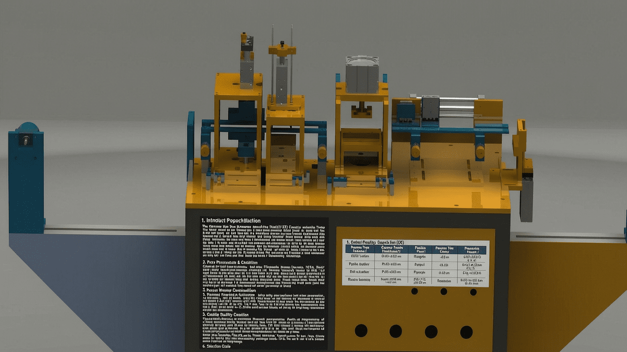
3. Core Process Parameter Control
3.1 Temperature, Pressure, and Time Settings
Optimal forming requires precise control of temperature (80–120°C), pressure (0.4–0.6 MPa), and dwell time (0.5–1.5 seconds). The machine’s heating system maintains ±2°C uniformity across the die. Higher temperatures reduce material stress but may cause warpage; lower temperatures risk incomplete forming. Pressure must be balanced to avoid flash or incomplete cavity definition. The CCD system monitors pocket formation and adjusts parameters in real time.
3.2 Process Window Optimization
For thin materials (0.3 mm), lower temperature (80°C) and higher pressure (0.6 MPa) with shorter dwell time (0.5 s) are recommended. For thicker materials (0.5 mm), increase temperature to 110°C and dwell time to 1.2 s while reducing pressure to 0.4 MPa to prevent die damage. The CCD system provides statistical process control (SPC) data, enabling operators to fine-tune parameters for minimal variation.
4. Common Issues & Troubleshooting
| Symptom | Root Cause | Solution |
|---|---|---|
| Pocket depth variation | Uneven temperature distribution | Check heater cartridge; recalibrate temperature controller |
| Pitch misalignment | Feeder encoder drift | Re-zero the encoder; verify mechanical coupling |
| Flash at cavity edges | Excessive pressure or worn die | Reduce pressure by 0.05 MPa; inspect die for wear |
| CCD false rejects | Lighting fluctuation or dirt on lens | Clean lens; adjust lighting intensity to factory default |
| Inconsistent sealing | Temperature or pressure fluctuation | Stabilize air supply; verify heater PID tuning |
5. Quality Inspection Standards
5.1 Incoming Quality Control (IQC)
Raw materials undergo visual inspection for contamination, thickness measurement (±0.02 mm), and peel strength test (≥0.5 N/cm for adhesive layer). Surface resistivity is verified using a megohmmeter. Dimensional checks include width tolerance (±0.1 mm) and hole position accuracy.
5.2 In-Process Quality Control (IPQC)
Sampling frequency is set at one sample per 1000 pockets. Acceptance criteria: pocket depth within ±0.05 mm, pitch error ≤0.03 mm, and no visible defects. The CCD system automatically rejects non-conforming pockets, and SPC charts track trends.
5.3 Reliability Testing
Aging test: 48 hours at 60°C to simulate long-term storage. High/low temperature cycling: -20°C to 80°C for 10 cycles. Transportation simulation: vibration test at 10–500 Hz for 2 hours. All tests require no delamination, cracking, or dimension change exceeding ±0.1 mm.
6. Selection Guide
| Component Type | Recommended Carrier Tape Width | Pocket Pitch | Machine Model | Key Feature |
|---|---|---|---|---|
| 0201/0402 resistors | 8 mm | 2 mm | KR-8CCD | High-speed CCD inspection |
| SOIC-8 ICs | 12 mm | 4 mm | KR-12CCD | Dual-cavity forming |
| QFP-44 | 24 mm | 8 mm | KR-24CCD | Deep pocket capability |
| Connectors (10-pin) | 16 mm | 4 mm | KR-16CCD | Anti-static brush option |
| Custom components | Up to 88 mm | Custom | KR-88CCD | Flexible tooling |
7. Conclusion
Kairuie’s self-designed carrier tape forming machine with CCD automatic measurement represents a leap forward in SMT packaging precision. By integrating real-time vision inspection with robust process control, it ensures consistent pocket geometry, reduces waste, and enhances production efficiency. The machine’s adaptability to various tape widths and materials makes it a versatile solution for electronics manufacturers. As a leader in SMT packaging materials, Kairuie Electronic Materials Co., Ltd. (www.kairuie.com) is committed to innovation and quality. We invite industry peers to exchange ideas and explore how our technology can optimize your packaging processes.


