凯瑞尔电子材料
1. Introduction
In the fast-paced world of SMT (Surface Mount Technology) electronics manufacturing, the packaging of sensitive electronic components into carrier tapes is a critical final step before storage, handling, and automated placement. Taping machines—also known as component taping or packaging machines—ensure that resistors, capacitors, inductors, ICs, connectors, and other miniature parts are precisely oriented, sealed, and wound onto reels, ready for high‑speed pick‑and‑place assembly lines. Selecting the right taping machine is not a one‑size‑fits‑all decision; production volume, component diversity, yield requirements, and budget constraints all heavily influence the ideal choice. This article provides a comprehensive technical comparison between semi‑automatic and fully automatic taping machines, with a special focus on small‑batch versus high‑volume production scenarios. We will explore the mechanical construction, material compatibility, critical process parameters, typical troubleshooting, quality inspection protocols, and a practical selection guide—all grounded in the proven solutions offered by Kairuie Electronic Materials Co., Ltd., including the Semi‑Automatic Manual Taping Machine, the CCD Semi‑Automatic Taping Machine, and the Fully Automatic CCD Taping Machine.
2. Product Structure & Material Composition
2.1 Overview of Taping Machine Architecture
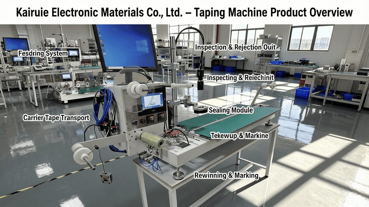
Despite the wide range of automation levels, all taping machines share a common core architecture designed to handle delicate SMT components with precision. The fundamental structure consists of a rigid base frame—typically fabricated from high‑grade aluminum profiles or stainless steel—to ensure vibration‑free operation and long‑term dimensional stability. Mounted on this frame are the following key subsystems:
- Feeding System: Depending on the machine type, this may be a manual loading station (semi‑automatic), a vibratory bowl feeder (fully automatic), or a combination of manual input with automated orientation. In the CCD Semi‑Automatic Taping Machine, components are manually placed onto a precision nest before being transferred to the carrier tape, while the Fully Automatic CCD Taping Machine employs a vibratory bowl that singulates and feeds parts automatically.
- Carrier Tape Transport: A motorized indexing mechanism advances the carrier tape (pocket tape) step‑by‑step. The machine accommodates standard tape widths from 8 mm to 56 mm, with custom versions expandable up to 88 mm—a feature offered across Kairuie’s machine range to support diverse component sizes.
- Inspection & Rejection Unit: The CCD Semi‑Automatic and Fully Automatic machines integrate a high‑resolution CCD camera system that inspects each component for orientation, position, and cosmetic defects before sealing. Non‑conforming parts are automatically ejected by a reject mechanism, ensuring only good components are packed.
- Sealing Module: The sealing station applies either heat‑activated or pressure‑sensitive cover tape. Kairuie’s machines stand out with a dual‑mode sealing capability—heat seal and self‑adhesive (pressure‑sensitive) can be selected with a simple switch, providing maximum flexibility for different cover tape materials and customer requirements.
- Rewinding & Marking: The sealed tape is wound onto a reel under controlled tension. In the Fully Automatic CCD Taping Machine, an automatic marking system (inkjet or laser) can print traceability codes, lot numbers, or barcodes directly on the cover tape, essential for high‑volume production with strict traceability demands.
2.2 Key Material and Component Details
The choice of materials and components directly influences the machine’s durability, contamination resistance, and process stability. All contact surfaces are typically made of ESD‑safe materials to protect static‑sensitive components. For example, the carrier tape guide rails are machined from stainless steel with a polished finish to minimize friction and particle generation. The precision nests in manual loading stations are often crafted from PEEK or Delrin to provide gentle component handling. Kairuie’s machines utilize high‑precision ball screws and linear guides for tape indexing, guaranteeing a positioning accuracy of ±0.05 mm or better, which is critical for pocket alignment. The CCD camera system employs telecentric lenses and advanced LED illumination to reliably inspect components as small as 0201 size (0.6 mm × 0.3 mm). Furthermore, the availability of dual sealing modes means that the same machine can be used with both heat‑seal cover tapes (requiring a heated shoe at typically 120‑200°C) and pressure‑sensitive adhesive tapes (requiring a pressure roller assembly), without any physical hardware changes. This versatility reduces the need for multiple dedicated machines and simplifies the changeover process.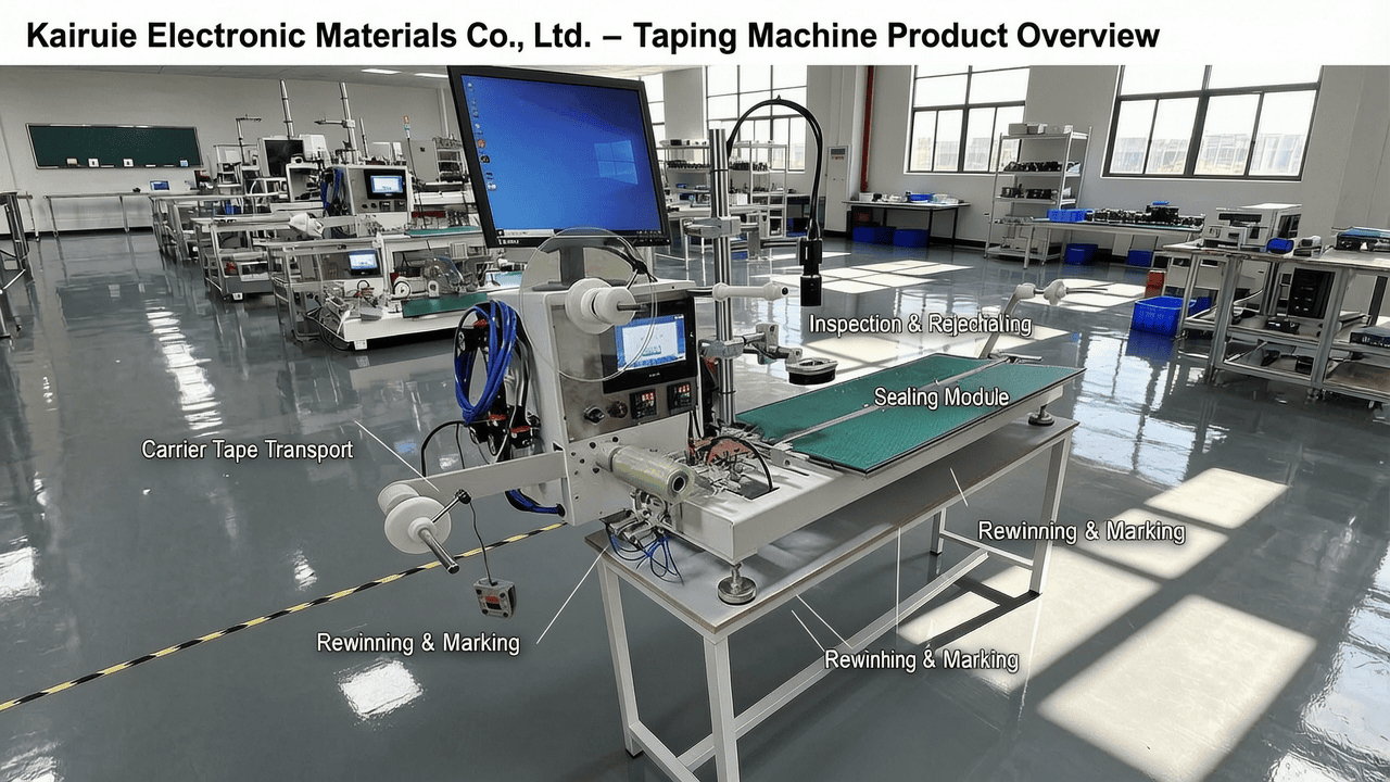
3. Core Process Parameter Control
3.1 Temperature Control in Heat Sealing
When using heat‑seal cover tape, temperature is the most critical parameter. The sealing nip consists of a heated shoe and a backing roller; the shoe temperature must be precisely controlled to melt the adhesive layer without damaging the carrier tape or component. Recommended temperature range is 130‑180°C, depending on the cover tape material (typical ESD‑PET films require 140‑160°C). A deviation of ±5°C can lead to weak seals or tape distortion. Kairuie taping machines incorporate a PID‑controlled cartridge heater with a thermocouple feedback loop, maintaining temperature stability within ±1°C. Real‑time temperature display and over‑temperature alarms protect against thermal runaway. It is advisable to set the temperature at the lower end of the manufacturer’s recommended range and gradually increase it until a consistent peel strength of 30‑80 gf (grams force) is achieved, as measured by a calibrated peel tester.
3.2 Pressure and Dwell Time Optimization
Sealing pressure and dwell time (the duration the cover tape is pressed against the carrier tape) work in tandem with temperature. Typical pressure settings range from 2 to 5 kg/cm². Insufficient pressure results in incomplete adhesive wetting and weak seals, while excessive pressure can crush the carrier tape pockets or cause adhesive squeeze‑out. Dwell time is usually between 0.3 and 1.5 seconds per seal. In high‑speed machines, this time is a limiting factor for throughput. For pressure‑sensitive cover tapes, the sealing force is applied by a spring‑loaded roller; the recommended nip pressure is 3‑4 kg/cm², and the process is room‑temperature. The Semi‑Automatic Manual Taping Machine often features a manual or pneumatic press, while the fully automatic models use servo‑controlled actuators to maintain consistent force and dwell independent of line speed. Process engineers should perform a Design of Experiments (DOE) varying temperature, pressure, and dwell to identify the process window that yields a peel strength of 40‑60 gf for most standard tapes, ensuring robust shipping and handling.
3.3 Indexing Speed and Tension Settings
Indexing speed—the rate at which the carrier tape advances—determines the machine’s throughput. For semi‑automatic machines, the operator‑controlled cycle might reach 3,000‑5,000 components per hour (cph), while the CCD semi‑automatic version can achieve 4,000‑6,000 cph due to faster inspection and reject integration. The Fully Automatic CCD Taping Machine can consistently run at 8,000‑15,000 cph or more, depending on component size and feeder performance. However, higher speeds demand tighter tension control on both supply and take‑up reels. Tape tension is generally maintained at 100‑300 gf to avoid stretching or de‑reeling. Kairuie’s automatic machines incorporate closed‑loop tension feedback using dancer rollers or load cells, automatically adjusting the rewind torque. Improper tension can lead to tape twisting, pocket deformation, or cover tape wrinkles. Regular calibration of tension sensors is recommended.
4. Common Issues & Troubleshooting
The following table summarizes frequent operational problems encountered in taping machines, their root causes, and effective corrective actions.
| Symptom | Root Cause | Solution |
|---|---|---|
| Incomplete or weak sealing (low peel strength) | Insufficient temperature, pressure, or dwell time; contaminated sealing shoe; incompatible cover tape | Verify and increase temperature by 5‑10°C; clean sealing shoe with isopropyl alcohol; increase pressure to 3‑4 kg/cm²; ensure cover tape adhesive matches carrier tape material |
| Carrier tape jamming or mis‑indexing | Dirty or worn sprocket holes; incorrect tape width setting; misaligned guide rails | Clean the transport path with compressed air; adjust guide rail width to match tape; replace worn drive sprockets; recalibrate the indexer home position |
| Component flipping or misorientation | Vibratory feeder amplitude too high; worn or improper tooling; insufficient vacuum in the pick‑up nozzle | Reduce feeder vibration amplitude; replace worn nests or nozzle tips; check vacuum level (should be > −0.6 bar); slow down pick‑and‑place motion |
| Cover tape wrinkles or bubbles | Excessive tape tension; uneven sealing pressure; trapped air during heat sealing | Reduce cover tape unwind tension; align sealing shoe parallel to tape; use a serrated or grooved sealing shoe to allow air escape; for PSA tapes, ensure roller is clean and free of debris |
| High false‑reject rate from CCD inspection | Incorrect inspection parameters; dirty lens or lighting; insufficient contrast | Recalibrate the CCD system with a golden sample; clean the camera lens and LED array; adjust exposure time and threshold; verify component color contrast against background |
5. Quality Inspection Standards
5.1 Incoming Quality Control (IQC)
Before a taping machine is released for production, or after major maintenance, a comprehensive IQC should be performed. This includes visual inspection of all critical surfaces for scratches, burrs, or contamination that could damage components. Dimensional verification using a calibrated caliper or coordinate measuring machine checks the flatness of the sealing shoe (±0.02 mm) and the alignment of the carrier tape path. The peel strength of the seal is the most direct quality indicator; using a standard peel tester (ASTM D3330 method), at least 10 samples should be pulled at a 180° angle at a constant speed of 300 mm/min. The average peel force must be within the specified range (typically 40‑80 gf for heat seal, 30‑60 gf for PSA). Additionally, ESD safety measurements confirm that all conductive parts are grounded with a resistance to ground of < 1 MΩ.
5.2 In-Process Quality Control (IPQC)
During continuous production, IPQC sampling ensures consistent quality. For semi‑automatic machines, a minimum of 1 reel per shift should be fully inspected for seal integrity, component orientation, and count accuracy. For high‑volume fully automatic lines, a sample of 2‑3 pockets from the beginning, middle, and end of each reel is recommended at a frequency of every 30 minutes. Acceptance criteria: zero visible broken seals, component lead coplanarity within 0.1 mm, and peel strength within ±15% of the target. Machine operators should also periodically verify the CCD inspection rejection rate; an abnormal increase may indicate component lot variation or system drift. All inspection data should be logged and trended using SPC (Statistical Process Control) to detect gradual wear of consumables like sealing shoes or cutting blades.
5.3 Reliability Testing
Beyond in‑line checks, reliability tests simulate real‑world logistics and environmental stresses. An aging test runs the machine continuously for 24‑48 hours, with periodic peel strength and dimensional checks to ensure no drift. Temperature cycling tests subject taped components to −40°C to +85°C cycles to verify seal integrity under thermal expansion. Transportation simulation using vibration tables (per ISTA standards) confirms that the component orientation is maintained and no cover tape lift occurs. Finally, component retention force after baking (e.g., 125°C for 4 hours) validates the tape’s suitability for subsequent soldering processes. Kairuie machines are designed to withstand these demanding tests, with proven reliability in automotive and industrial electronics applications.
6. Selection Guide
Choosing between semi‑automatic and fully automatic taping machines depends primarily on production volume, component variety, and quality/inspection requirements. The following table provides a decision matrix based on typical industry profiles.
| Application Scenario | Recommended Machine | Key Considerations |
|---|---|---|
| Low‑volume, high‑mix production (prototyping, niche components, < 10,000 cph needed) | Semi‑Automatic Manual Taping Machine | Cost‑effective, quick changeover, manual loading suitable for odd‑shaped components, no CCD but visual inspection by operator, ideal for in‑house lab or small EMS |
| Medium‑volume with strict quality requirements (5,000‑30,000 cph, many component types) | CCD Semi‑Automatic Taping Machine | Manual placement but automated CCD inspection and rejection ensure zero‑defect packaging, dual sealing mode, flexible tape width up to 56 mm, good for automotive or medical components |
| High‑volume, dedicated component lines (> 30,000 cph, single component type or few variants) | Fully Automatic CCD Taping Machine with Marking | Vibratory bowl automatic feeding, CCD inspection, reject, automatic marking and sealing—minimizes labor, ensures traceability, highest throughput, quick ROI for large batches |
| Extra‑wide components (e.g., 72 mm, 88 mm) | Customized CCD Semi‑Automatic or Fully Automatic | Kairuie can extend tape width up to 88 mm on request; for large connectors or transformers, semi‑automatic with CCD is often preferred to avoid delicate vibratory feeding damage |
Beyond batch size, consider future scalability. The CCD Semi‑Automatic Taping Machine can often be upgraded with an automatic feeder at a later stage, protecting the initial investment. All Kairuie machines support both heat seal and self‑adhesive cover tapes, eliminating the need for separate sealing units. The dual‑mode feature alone can save thousands of dollars in equipment and floor space.
7. Conclusion
The decision between semi‑automatic and fully automatic taping machines is a strategic one that impacts production efficiency, quality assurance, and overall operating costs. For small batches and high‑mix environments, the Semi‑Automatic Manual Taping Machine offers unmatched simplicity and low initial investment, while the CCD Semi‑Automatic version adds a critical layer of automated inspection for zero‑defect packaging. For high‑volume, dedicated production lines, the Fully Automatic CCD Taping Machine with integrated marking delivers the speed, traceability, and labor savings required to stay competitive. Regardless of choice, the versatility of dual‑mode sealing (heat seal and pressure‑sensitive) and wide carrier tape compatibility (8 mm to 88 mm) ensures that Kairuie’s taping solutions adapt to evolving component packaging needs. As a leading provider of SMT electronic packaging materials and equipment, Kairuie Electronic Materials Co., Ltd. (www.kairuie.com) is committed to supporting the electronics manufacturing industry with reliable, innovative, and cost‑effective taping solutions. We invite engineers, production managers, and industry peers to reach out and exchange ideas on optimizing your component packaging process—together, we can build smarter, more efficient manufacturing flows.


