凯瑞尔电子材料
1. Introduction
In the realm of Surface Mount Technology (SMT), the relentless drive toward miniaturization and higher integration densities has placed unprecedented demands on electronic packaging materials. Microchips, with their shrinking feature sizes and delicate circuitry, are increasingly vulnerable to electrostatic discharge (ESD) events that can cause latent or catastrophic failures. Carrier tapes and cover tapes, as the primary transport and storage media for SMT components, play a pivotal role in safeguarding these sensitive devices throughout the manufacturing and assembly lifecycle. However, not all carrier tape systems are created equal. Many conventional materials exhibit wide variations in surface resistivity, leading to unpredictable static dissipation and potential device damage.
Enter Kairuie Electronic Materials Co., Ltd.’s PS (Polystyrene) Black Conductive Carrier Tape and Anti-Static Shielding Cover Tape—a purpose-engineered solution that delivers exceptional ESD control with a surface resistivity steadfastly maintained within the 106 to 109 Ω range. Combined with a sealing peel force that demonstrates minimal fluctuation, this system provides comprehensive protection against electrostatic threats. This technical article delves into the structural composition, critical process parameters, quality assurance protocols, and selection criteria for these advanced packaging materials. By illuminating the science behind their stable performance, we aim to equip SMT engineers, process specialists, and quality managers with the knowledge to optimize their component handling and eliminate costly ESD-related defects.
2. Product Structure & Material Composition
2.1 PS Black Conductive Carrier Tape: Layer Architecture
The PS black conductive carrier tape (e.g., Kairuie model KRE-PS-BC series) is a monolayer or co-extruded structure engineered for uniform static dissipation. At its core is a high-impact polystyrene (HIPS) matrix, selected for its excellent thermoforming characteristics, dimensional stability, and compatibility with high-speed taping equipment. Conductive carbon black is dispersed throughout the polymer at a loading level optimized to achieve target resistivity without compromising mechanical integrity. This homogeneous dispersion ensures that every surface of the pocket—sidewalls and bottom—exhibits consistent static-dissipative properties, eliminating localized “hot spots” that could accumulate charge.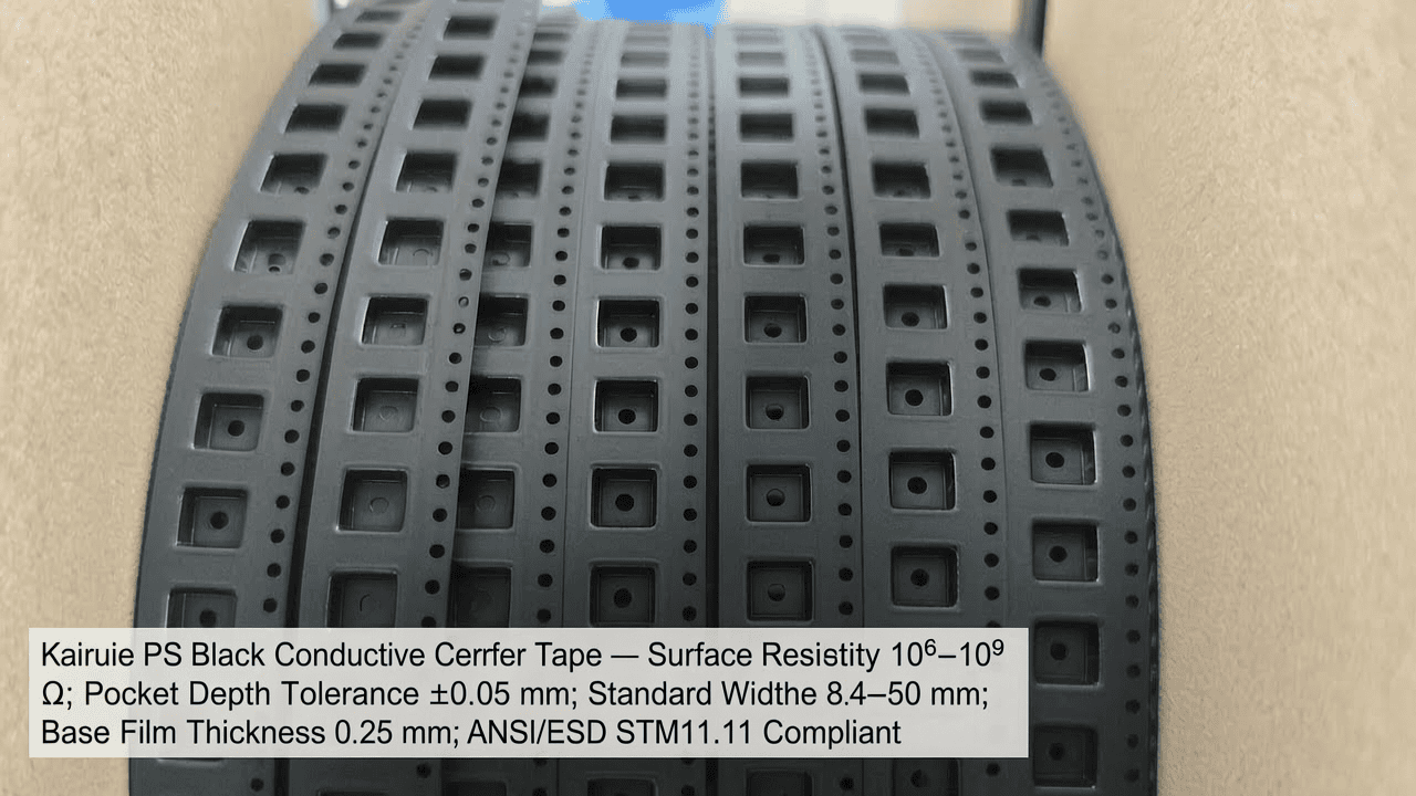
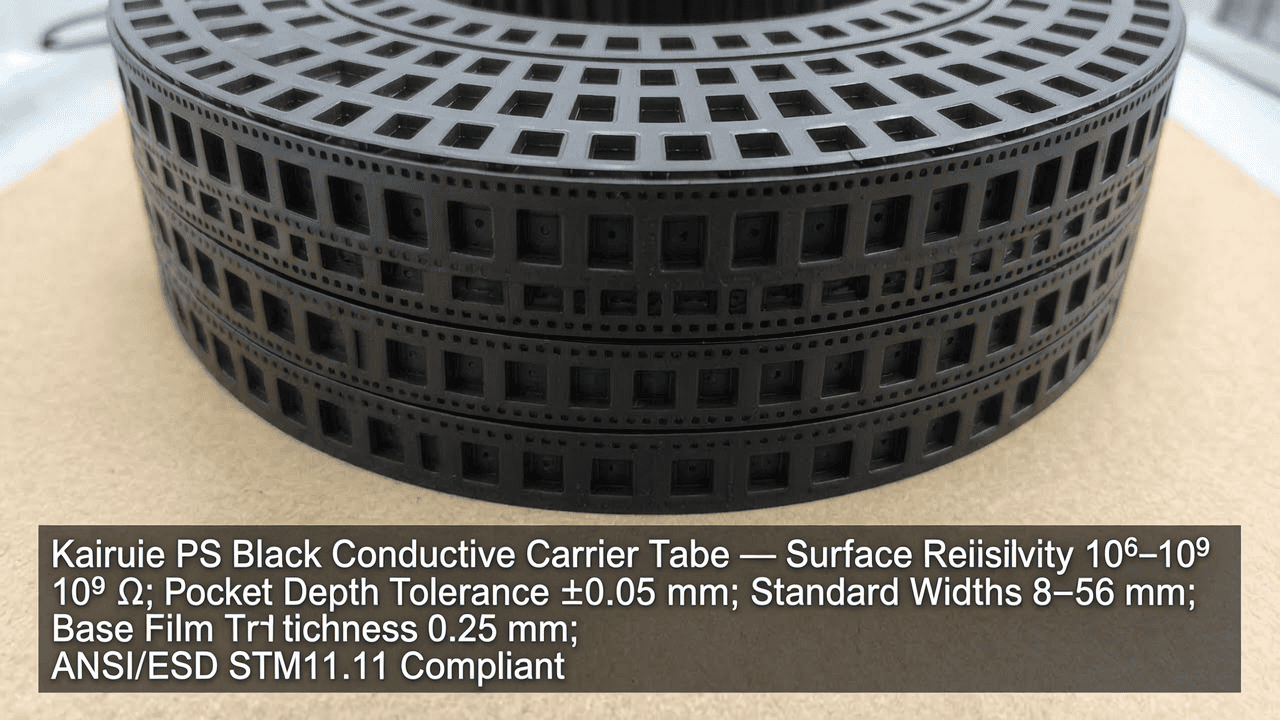
The tape is formed with precision pockets tailored to component dimensions. Kairuie’s advanced extrusion and thermoforming processes maintain a pocket depth tolerance of ±0.05 mm and a pocket pitch accuracy of ±0.1 mm, critical for pick-and-place reliability. Standard tape widths range from 8 mm to 56 mm, with the 8 mm version (KRE-PS-BC08) and 12 mm version (KRE-PS-BC12) being the most common for microchips. The base film thickness is typically 0.25 mm, providing sufficient rigidity to prevent pocket deformation during handling and reeling. Surface resistivity, measured per ANSI/ESD STM11.11, is rigorously controlled between 5×10⁵ and 9×10⁹ Ω, with a nominal target of 107 Ω—the sweet spot for rapid charge dissipation without risking leakage currents that could impair device performance.
2.2 Anti-Static Shielding Cover Tape: Dual-Function Design
The complementary anti-static shielding cover tape (KRE-ASC series) is a multi-layer laminate that provides not only mechanical closure but also active static management. The top layer consists of a biaxially oriented polyester (PET) film with a thickness of 20 μm to 50 μm, depending on tensile strength requirements. This PET layer is treated with a permanent anti-static coating on the outer surface, yielding a surface resistivity of 106 to 1011 Ω. Beneath it lies a buried metalized layer (typically aluminum) that acts as a Faraday cage, shielding components from external electric fields. The inner heat-seal layer is a specially formulated acrylic or synthetic rubber adhesive with tailored melt flow properties to achieve a consistent peel force.
The adhesive layer is the cornerstone of sealing performance. Kairuie’s proprietary adhesive formulation ensures that when heat is applied during the cover tape sealing process, it flows uniformly and wets the carrier tape’s edge rails without excessive squeeze-out or void formation. This results in a peeling force that typically falls within a tight band of 30–70 g for a 8 mm tape (0.3–0.7 N), compliant with EIA-481 standards. Crucially, this peel force remains stable over time and after exposure to temperature cycling, preventing unexpected cover tape delamination or difficult peel that can slow down component placement.
2.3 Material Parameter Comparison
| Parameter | PS Black Conductive Carrier (KRE-PS-BC08) | Anti-Static Cover Tape (KRE-ASC40) |
|---|---|---|
| Base Material | High-Impact Polystyrene with carbon black | PET / Aluminum / Acrylic adhesive |
| Thickness (Carrier Base) | 0.25 mm ±0.02 mm | 0.048 mm ±0.005 mm (total) |
| Surface Resistivity | 106–109 Ω (target 107 Ω) | Outer: ≤1011 Ω; Inner adhesive: insulative |
| Pocket Dimensional Tolerance | ±0.05 mm (depth), ±0.1 mm (pitch) | N/A |
| Thermal Stability | Continuous use to 60°C; peak 80°C | Sealing temp up to 200°C (short duration) |
| Peel Force (to carrier) | N/A | 0.3–0.7 N (30–70 gf) for 8 mm tape |
3. Core Process Parameter Control
3.1 Sealing Process Parameters and Their Influence
Attaining the ideal peel force and maintaining the ESD integrity of the packaging requires precise control over the heat-sealing operation. The three primary variables—temperature, pressure, and dwell time—must be carefully balanced within narrow process windows. For Kairuie’s PS black conductive carrier tape and anti-static shielding cover tape, the recommended parameters for a typical rotary or reciprocating sealer are: sealing temperature between 140°C and 190°C, applied pressure of 0.4–0.6 MPa, and dwell time of 0.4–0.8 seconds. These ranges ensure that the adhesive reaches adequate flow temperature to bond with the carrier’s edge rails without inducing thermal damage to the tape structure or causing excessive adhesive migration into the pocket area.
Temperature: If the sealing temperature is too low (<130°C), the adhesive does not activate sufficiently, leading to weak bonds and the risk of cover tape lifting during transport. Peeling force may drop below 20 gf, making the seal unreliable. Conversely, temperatures exceeding 200°C can degrade the PET film, causing it to shrink or become brittle, and may also carbonize the adhesive, increasing peeling force above 120 gf and making tape removal difficult at the placement machine. This can cause component mis-picks or residue on the carrier tape rails.
Pressure: Adequate pressure ensures intimate contact between the cover tape adhesive and the carrier tape surface, but excessive pressure can deform the pocket openings, especially in thinner tape profiles. For 8 mm tape, a pressure of 0.5 MPa is often the sweet spot, providing uniform seal line width without distorting the pocket geometry. Kairuie’s carrier tape is designed to withstand typical sealing pressures without pocket brim indentation, thanks to the robust PS formulation.
Dwell Time: The sealing dwell time must be sufficient to transfer heat through the cover tape and into the adhesive layer. Insufficient dwell results in incomplete bond formation; excessive dwell can cause adhesive squeeze-out and accumulation on the sealing head. Modern high-speed sealers operate with dwell times as low as 0.3 seconds, but for consistent peel force, 0.5 seconds is recommended as a baseline. Process optimization should always be performed using design of experiments (DOE) to map the response surface of peel force against the three parameters.
3.2 Process Window Optimization for ESD Performance
Interestingly, the sealing process has a secondary effect on the ESD performance of the package. Overheating can alter the resistivity of the carrier tape’s surface near the seal line due to thermal oxidation of the carbon black. Therefore, Kairuie recommends validating surface resistivity after sealing on sample parts, especially at the maximum temperature limit. A robust process window with a Cpk >1.33 for peel force and consistent resistivity readings is a hallmark of a well-optimized line. Additionally, the ambient environment plays a role: relative humidity should be maintained between 30% and 60% to avoid moisture condensation on the tapes, which can transiently lower surface resistivity and alter peel forces.
4. Common Issues & Troubleshooting
Even with best-in-class materials, variations in machine condition, operator technique, or ambient factors can lead to quality problems. The table below outlines the most frequently encountered issues when using PS black conductive carrier tape and anti-static shielding cover tape, along with root causes and corrective actions.
| Symptom | Root Cause | Solution |
|---|---|---|
| Cover tape peeling force too low, sporadic lifting | Insufficient sealing temperature, contaminated sealing head, adhesive beyond shelf life, or excessive line speed | Verify and adjust temperature to 150–180°C; clean sealing wheel regularly; check adhesive lot date; reduce speed to increase dwell time. |
| Cover tape peels with excessive force (>100 gf), causing component disruption | Temperature too high, too much pressure, or dwell time too long; adhesive bleed into pocket | Reduce temperature in 5°C increments; decrease pressure to 0.4 MPa; shorten dwell to 0.4 s; ensure cover tape width matches carrier tape rail width. |
| Static charge buildup on pocket surfaces after sealing (resistivity >1010 Ω) | Degradation of carbon black dispersion due to overheating; contamination from sealing residues; tape stored in very dry environment (<10% RH) | Confirm sealing temperature does not exceed 190°C; clean sealing area to remove oxidized carbon; condition tape at 23°C/40% RH for 24 h before use; test resistivity of sealed pockets. |
| Interior of pocket deformed, component does not fit or sits tilted | Excessive sealing pressure deforming brim; carrier tape gauging too thin; improper pocket formation during thermoforming | Reduce sealing pressure; check carrier tape thickness with micrometer; inspect incoming tape for pocket dimensions; switch to thicker base material (0.3 mm) if needed. |
| Cover tape leaves adhesive residue on carrier tape after peeling | Over-curing of adhesive at high temperature or prolonged dwell; adhesive incompatible with carrier surface treatment | Optimize temperature/dwell; switch to a cover tape with a low-residue adhesive formulation (e.g., KRE-ASC40-LR); ensure carrier tape edge rails are clean and have appropriate surface energy. |
5. Quality Inspection Standards
5.1 Incoming Quality Control (IQC)
Upon receipt, every batch of Kairuie carrier tape and cover tape undergoes rigorous IQC to ensure it meets specification. Visual inspection under 30× magnification checks for pinholes, delamination, uneven carbon black dispersion (agglomerates), and pocket consistency. Dimensional measurements using a profile projector or coordinate measuring machine verify pocket length, width, depth, and pitch according to EIA-481 tolerances. The most critical test is surface resistivity: a four-point probe or concentric ring electrode is used per ASTM D257, and readings must fall within 106–109 Ω. Peel strength is tested on a tensile tester by sealing a sample cover tape to the carrier under standard conditions and measuring the force required to peel at 180°, speed 300 mm/min; values should lie within the product specification band (e.g., 0.3–0.7 N for 8 mm).
5.2 In-Process Quality Control (IPQC)
During tape-and-reel operation, IPQC checks are performed at a frequency of once per hour or once per reel change. Operators measure the actual sealing temperature with a surface thermocouple, the peel force using a handheld peel tester, and visually inspect the seal line for continuity. The peel force is recorded on an X-bar-R chart to detect process drift. Additionally, the ESD coordinator periodically measures the surface resistivity of the carrier tape pockets post-sealing to verify that the heat cycle has not elevated resistivity beyond the acceptable limit. Acceptance criteria mirror IQC specifications, with an added requirement that no components exhibit visible damage or misalignment in the sealed pockets.
5.3 Reliability Testing
To simulate handling and storage stresses, Kairuie performs accelerated life testing on sealed samples. An aging test at 85°C/85% relative humidity for 168 hours assesses hydrolytic stability and maintains peel force within ±20% of initial. Thermal cycling between -40°C and +85°C for 100 cycles (30 min dwell) verifies that the seal integrity and resistivity remain stable. A transportation vibration test following IEC 60068-2-6 subjects packaged reels to 10–500 Hz sweep at 2 g for 1 hour per axis; after which the peel force must not degrade and no cover tape detachment is permitted. Finally, a component-free-fall test ensures the system survives drops from 1 meter without opening. These reliability benchmarks give end-users confidence that Kairuie tapes will protect components from factory floor to insertion into the PCB.
6. Selection Guide
Selecting the appropriate carrier tape and cover tape combination depends on the component type, sensitivity, and application environment. The table below provides a quick reference guide based on common SMT components and the corresponding recommended Kairuie products.


