凯瑞尔电子材料
1. Introduction
In the high-precision world of Surface Mount Technology (SMT), the seamless delivery of tiny electronic components to pick-and-place machines is critical. While much attention focuses on soldering pastes, stencils, and reflow ovens, the carrier tape plays an indispensable role as the “invisible hero” of automated assembly. Without standardized, reliable carrier tapes, the entire tape-and-reel packaging ecosystem would falter, leading to component loss, mis-pickups, and production downtime. This article delves into the technical nuances of carrier tapes, from material science to process control, and highlights how Kairuie Electronic Materials Co., Ltd. ensures uncompromised quality for SMT applications. We will explore product structure, critical process parameters, troubleshooting common defects, inspection standards, and selection guidelines, all referencing specific model numbers and parameters where applicable. Central to our discussion is the EIA-481 industry standard, which governs embossed and punched carrier tapes from 8 mm to 200 mm widths, ensuring compatibility across feeders and high-volume production lines.
2. Product Structure & Material Composition
2.1 Layer Architecture and Materials
A carrier tape is not a monolithic strip but a carefully engineered laminate. For embossed types (Kairuie KT-E series), the structure comprises a base film, typically polyethylene terephthalate (PET), chosen for its dimensional stability, strength, and heat resistance. The PET thickness varies by application: 0.25 mm for standard 8 mm tapes (KT-E0804-PET), 0.30 mm for 12 mm and wider versions (e.g., KT-E1208-PET). A critical attribute is the surface resistivity, which is modified using a permanent anti-static coating to maintain values between 10^6 and 10^8 ohms/sq, preventing electrostatic discharge (ESD) damage to sensitive components. The pockets are thermoformed with high precision, achieving depth tolerances of ±0.05 mm. Punched paper carrier tapes (KT-P series) employ a composite paper base (0.40–0.50 mm thick) with a polyethylene (PE) or polypropylene (PP) lamination for enhanced tear resistance. The surface resistivity target is slightly higher, ≤ 10^10 ohms/sq, suitable for less ESD-sensitive passives. A pressure-sensitive adhesive (PSA) layer is applied to the top surface for heat-activated cover tape sealing, with peel strength adjustable from 30 to 80 grams as per EIA-481.
2.2 Key Specifications and Models
Kairuie offers several standard models tailored to industry needs: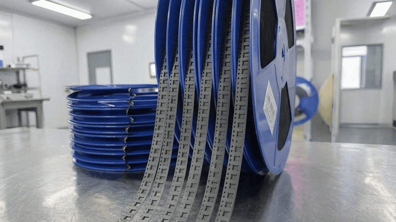
- KT-E0804-PET: Embossed tape, 8 mm width, 4 mm pitch, pocket depth 1.0–2.5 mm, for small chip components (0402, 0603). PET thickness 0.25 mm, surface resistivity 10^6–10^8 ohms/sq.
- KT-E1208-PET: 12 mm width, 8 mm pitch, pocket depth up to 4.0 mm, used for ICs and connectors. PET thickness 0.30 mm.
- KT-P0812-Paper: Punched paper tape, 8 mm width, 4 mm pitch (2 mm component pitch via double punching), paper thickness 0.45 mm, surface resistivity ≤ 10^10 ohms/sq, for chip resistors and capacitors.
- KT-P1216-Paper: 12 mm paper tape, 8 mm pitch, for larger passive arrays or inductors.
Dimensional accuracy is paramount: pocket width tolerance is ±0.1 mm, and cumulative pitch error over 10 pockets must not exceed 0.2 mm. These parameters ensure flawless feeding and placement at speeds exceeding 30,000 components per hour.
3. Core Process Parameter Control
3.1 Sealing Temperature and Its Impact
The cover tape sealing process is the linchpin of reliable component retention. Temperature directly influences the adhesive activation and consequently peel strength. For Kairuie’s PSA-coated tapes, the recommended sealing temperature ranges from 130°C to 170°C, depending on line speed and material. A lower temperature (e.g., 130°C) may lead to incomplete bonding, resulting in premature cover tape lifting during reeling—a common source of component loss. Conversely, exceeding 180°C risks thermal degradation of the PET or paper base, causing brittleness or warpage. At the optimal 150°C ± 10°C, the peel force stabilizes between 40–70 g, meeting EIA-481 requirements for both mechanical retention and easy peel-off by the pickup nozzle. Real-time monitoring with infrared sensors is recommended to maintain consistency.
3.2 Pressure and Dwell Time Optimization
Sealing pressure, typically applied via a heated roller or platen, should be set between 2.5–4.0 kg/cm². Too little pressure causes weak adhesion; too much can deform pockets, altering component orientation. Dwell time—the contact duration—is a function of line speed. At a typical speed of 3 meters per minute, a dwell time of 0.2–0.5 seconds suffices. For high-speed lines (5 m/min), increase temperature slightly (160°C) and pressure to 3.5 kg/cm² to maintain bond integrity without sacrificing throughput. A process window study on KT-E1208-PET revealed that a 10% variation in pressure is tolerable, but exceeding 4.5 kg/cm² reduces pocket depth by up to 0.05 mm, potentially causing component jamming.
3.3 Environmental and Material Handling
Ambient conditions during packaging also matter. Relative humidity above 60% can cause paper tapes to absorb moisture, leading to swelling and dimensional instability. Storage at 20–25°C and 40–50% RH is advised. For embossed PET tapes, humidity is less critical, but static control is essential; ionizing bars should be positioned near the sealing station to neutralize any charge buildup. These parameters collectively form a robust process window, ensuring first-pass yield above 99.5% for Kairuie tapes.
4. Common Issues & Troubleshooting
4.1 Defect Analysis and Solutions
| Symptom | Root Cause | Solution |
|---|---|---|
| Cover tape delamination during reeling | Insufficient sealing temperature or pressure; contaminated adhesive layer | Increase temperature to 150–170°C, verify pressure at 3.0 kg/cm²; clean rollers and inspect tape for oil residue |
| Component flipping or tombstoning inside pocket | Pocket dimensions too large for component; tape camber causing twisting | Select correct pocket size (e.g., 0201 component uses KT-E0804 with 0.8×0.4 mm pocket); check tape flatness (camber <1 mm per 250 mm) |
| Excessive peel force causing pickup failures | Overtemperature or overpressure during sealing; aged adhesive | Reduce temperature by 5–10°C; ensure tape freshness (use within 6 months of manufacture); test peel force to maintain 40–70 g |
| Static charge attracting dust or causing mispick | Surface resistivity out of spec due to coating wear or humidity | Measure resistivity; if >10^10 ohms/sq, replace with fresh tape; use ionizers; confirm anti-static treatment per KT-E/P specifications |
| Tape breakage during high-speed feeding | Paper tape exceeding tensile strength; nicks or edge damage | Upgrade to PET tape (KT-E) for demanding applications; inspect sprocket holes; tensile strength ≥ 5 N for paper tape per EIA-481 |
Proactive monitoring and adherence to the recommended process window prevent most of these issues. Kairuie provides detailed datasheets with each shipment, including batch-specific peel force and resistivity test results.
5. Quality Inspection Standards
5.1 Incoming Quality Control (IQC)
Upon receipt, each lot of Kairuie carrier tape undergoes rigorous IQC. Visual inspection checks for defects such as cracks, discoloration, or foreign particles under 10x magnification. Dimensional conformity is verified using a coordinate measuring machine (CMM): pocket width, depth, pitch, and tape width are measured against the drawing, with AQL 0.65 per MIL-STD-1916. A key performance test is peel strength: a sample of sealed cover tape is pulled at 300 mm/min on a tensile tester; values must fall within 40–80 g for embossed tapes and 30–60 g for paper tapes. Surface resistivity is checked using a concentric ring probe per ASTM D257; readings outside the specified range trigger lot rejection.
5.2 In-Process Quality Control (IPQC)
During the packaging process at the customer site, IPQC sampling is performed every 2 hours or after every 5,000 components, whichever comes first. The acceptance criteria are identical to IQC, with additional checks for tape camber (≤1 mm per 250 mm length) and sprocket hole integrity. If any parameter is out of tolerance, the preceding production segment is quarantined for rework or scrap. Kairuie supports on-site audits with a dedicated quality engineer hotline.
5.3 Reliability Testing
Ensuring long-term stability, Kairuie conducts the following reliability tests on production batches:
- Thermal aging: Samples are exposed to 85°C for 72 hours; peel force must not deviate more than 15% from initial.
- High/low temperature cycling: -40°C to +85°C, 50 cycles; no cracking or delamination.
- Transportation simulation: Packed reels are vibrated at 10–50 Hz, 1G for 30 minutes per ISTA 2A; components must not shift or escape pockets.
These tests guarantee that Kairuie carrier tapes perform reliably from factory to end-user, even under extreme logistics conditions.
6. Selection Guide
6.1 Matching Tape to Component Type
Selecting the right carrier tape is a balance between component requirements, cost, and process capability. The table below summarizes Kairuie’s recommendations.
| Component Category | Typical Component Size | Recommended Tape Model | Key Features |
|---|---|---|---|
| Chip Resistors/Capacitors (0201/0402) | 0.6×0.3 mm, 1.0×0.5 mm | KT-P0812-Paper (8 mm) or KT-E0804-PET | Paper for cost-effectiveness; PET for ESD-sensitive or high-speed lines |
| LEDs (PLCC, small SMD) | 1.5×1.5 mm to 3.5×2.8 mm | KT-E0804-PET (8 mm, depth ≤1.5 mm) | Clear PET optional to protect lead; anti-static mandatory |
| Small ICs (SOT-23, SC-70) | 2.9×1.3 mm to 2.0×1.25 mm | KT-E1208-PET (12 mm) | Deeper pocket (2.0–3.0 mm) to accommodate package height; reinforced PET |
| Connectors (micro USB, board-to-board) | Up to 30×10 mm | KT-E2416-PET (24 mm or wider custom) | Wide tape, thick PET (0.35–0.50 mm); deep pocket up to 8 mm |
| Large Passives (power inductors) | 6×6 mm and above | KT-E1632-PET (16 mm or 24 mm) | Embossed with retention pockets to secure heavy parts; peel force >50 g |
For high-volume, low-cost applications (e.g., chip resistors), paper tapes (KT-P series) offer 20–30% cost savings. For precision or moisture-sensitive devices, PET embossed tapes (KT-E) provide superior dimensional stability and ESD protection. Kairuie also offers custom pocket designs for odd-shaped components, with lead times as short as 2 weeks.
7. Conclusion
The carrier tape is far more than a simple strip of plastic or paper; it is a precision-engineered packaging solution that directly influences SMT line efficiency, yield, and component reliability. Kairuie Electronic Materials Co., Ltd. stands at the forefront of this technology, delivering EIA-481 compliant carrier tapes that meet the most stringent requirements of the electronics manufacturing industry. From the carefully selected PET and paper substrates to the meticulous control of resistivity, dimensions, and peel force, every detail of our KT-E and KT-P series reflects a commitment to quality. Our continuous investment in R&D and customer support ensures that, whether you are packaging microscopic 01005 chips or bulky connectors, there is a Kairuie solution ready to optimize your process. We invite you to explore our full product range and collaborate with our technical team to tailor a packaging strategy that fits your unique needs. Visit us at www.kairuie.com or contact us for a sample evaluation. Together, let’s advance the art of SMT packaging, one tape at a time.


