凯瑞尔电子材料
1. Introduction
In the precision-driven world of surface-mount technology (SMT), carrier tape serves as the critical packaging medium that ensures secure transportation, automated feeding, and reliable placement of electronic components. From minuscule 01005 chip resistors to large connectors, the choice of carrier tape directly impacts pick-and-place efficiency, component protection, and manufacturing yield. Among the many design considerations, the color of the tape—transparent versus black—often sparks debate among engineers and procurement specialists. Is there a performance difference? Does color affect electrical or mechanical properties? This article demystifies the topic, providing a deep dive into the material science, process control, troubleshooting, and selection criteria for carrier tape color, backed by industry-standard parameters and Kairuie Electronic Materials’ product expertise. We will explore how transparent and black carrier tapes each fit specific application scenarios, ensuring you make an informed decision that optimizes your SMT line.
2. Product Structure & Material Composition
2.1 Layer Architecture and Material Selection
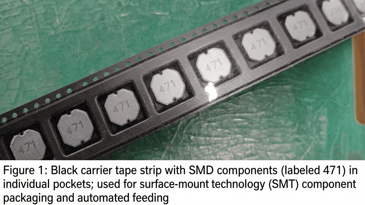
Modern carrier tape is a multi-layered engineered film designed for dimensional stability, static dissipation, and reliable component retention. The primary substrate is typically polyethylene terephthalate (PET), chosen for its excellent tensile strength, thermal resistance, and transparency. A standard carrier tape consists of at least three functional layers: the base layer (PET film), an adhesive layer for pocket formation (if thermoformed or embossed), and an optional top coating for surface resistivity control. Kairuie’s KAI-TP series, for instance, utilizes a biaxially oriented PET film with a thickness ranging from 0.2 mm to 0.5 mm depending on pocket depth and component weight. The base PET layer provides a tensile strength of ≥150 MPa and elongation at break of ≤120%, ensuring the tape withstands the rigors of high-speed unwinding. An anti-static or static-dissipative coating is applied to achieve a surface resistivity of 106 to 109 Ω/sq, compliant with ANSI/ESD S20.20 standards. For adhesive layers, acrylic or silicone pressure-sensitive adhesives (PSA) are used, with peel strength to stainless steel of 0.5–1.5 N/mm. The color of the tape is determined by the base PET—either left naturally transparent for optical clarity or pigmented black with carbon or other light-blocking additives. It is critical to note that for the same material formulation, the color does not alter mechanical or electrical characteristics; a black PET carrier tape exhibits identical tensile modulus and surface resistivity as its transparent counterpart.
2.2 Key Material Parameters and Color Independence
Extensive testing confirms that the optical tint of the PET substrate does not affect core physical properties. Kairuie’s quality assurance data for the KAI-TP-3000 (transparent) and KAI-TP-3000B (black) show indistinguishable values: thickness tolerance ±0.02 mm, surface roughness Ra ≤0.4 µm, and coefficient of friction (COF) 0.3–0.5. Electrical parameters such as surface resistivity remain within 106–109 Ω/sq regardless of color, as the anti-static coating is applied identically. Differential scanning calorimetry (DSC) analysis reveals a glass transition temperature (Tg) of approximately 78°C for both variants, ensuring stable pocket geometry up to 60°C ambient temperatures. Thus, the choice between transparent and black tape should be driven by application-specific requirements rather than concerns about material degradation.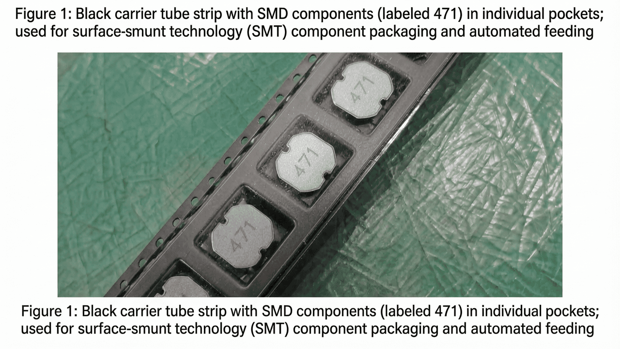
3. Core Process Parameter Control
3.1 Temperature, Pressure, and Time in Sealing Operations
Carrier tape performance is intimately linked to the heat-seal process that attaches the cover tape. Typical sealing parameters recommended by Kairuie for both transparent and black tapes are: temperature 130°C–180°C, pressure 0.3–0.5 MPa, and dwell time 0.2–0.5 seconds. The exact window depends on cover tape material and line speed. At 150°C, a pressure of 0.4 MPa for 0.3 seconds yields a seal strength of 40–80 g/20 mm, ensuring component retention during transport while allowing smooth peel by the pick-and-place machine. Excessive temperature (>190°C) causes PET crystallization and embrittlement, potentially distorting pockets. Insufficient temperature (<120°C) results in weak seals and tape pop-corning during reflow. Pressure uniformity is critical; variations beyond ±0.05 MPa across the sealing bar cause intermittent peeling failures. Dwell time must balance throughput and bond integrity; too short (<0.15 s) leads to incomplete bonding, while too long (>0.6 s) may shrink the PET film, altering pocket dimensions. Process engineers should perform Design of Experiments (DoE) to define optimal parameters and implement closed-loop control with thermocouple feedback for consistent seam quality.
3.2 Impact of Process Parameters on Color-Specific Performance
While the base material is color-agnostic, the visual feedback during setup and monitoring differs. Transparent tape allows direct observation of component placement and seal integrity through the base, enabling quicker detection of misalignment or incomplete sealing. Black tape, however, may mask such issues, necessitating more frequent destructive testing or automated vision systems with backlighting. Thermal absorption can vary slightly: black tape may absorb more radiant heat from sealing bars, potentially allowing a 5–10°C lower setpoint, but this difference is negligible in practice. Kairuie recommends validating the sealing recipe separately for black tapes in high-speed lines (>30,000 pockets/hour) to account for minor thermal inertia changes. Process window optimization should include a safety margin of ±10°C and ±0.05 MPa around the nominal center point.
4. Common Issues & Troubleshooting
Field experience reveals several recurring challenges when deploying carrier tape. The table below outlines five typical problems, their root causes, and practical solutions—including those related to color choice.
| Symptom | Root Cause | Solution |
|---|---|---|
| Component sticking to cover tape during pick-up | Excessive seal strength due to high temperature/pressure; low-quality cover tape adhesive | Reduce sealing temperature by 5–10°C; verify cover tape peel force (target 40–80 g/20 mm); store tapes at 20–25°C, 40–60% RH to prevent adhesive aging |
| Visual inspection of component orientation fails | Opaque black tape blocks camera-based orientation checks | Switch to transparent KAI-TP-3000 tape; if light-sensitivity requires black, implement side-view cameras or X-ray inspection |
| Pocket deformation or collapse during transport | Inadequate PET thickness for component weight; thermal softening during reflow | Upgrade to 0.3 mm or 0.4 mm thick PET (KAI-TP-4000 series); ensure tape anti-static coating withstands 150°C peak reflow temperature |
| Electrostatic discharge (ESD) damage to components | Surface resistivity out of spec (>1012 Ω/sq) or worn-out conductive layer | Confirm resistivity with calibrated meter; specify static-dissipative tape with 106–109 Ω/sq; avoid black tapes with purely cosmetic carbon fillers that lack uniform dissipation |
| Tape splitting or splicing failures | Brittleness from low humidity storage; improper splice tape adhesion | Condition tapes at 30–50% RH for 24h before use; use Kairuie’s KAI-SPLICE-500 series splice tools with optimized pressure (0.5 MPa) |
5. Quality Inspection Standards
5.1 Incoming Quality Control (IQC)
Rigorous IQC ensures that carrier tape meets design specifications before production. For both transparent and black tapes, inspections include: visual examination for defects (wrinkles, gels, fish-eye imperfections) under 30x magnification; dimensional checks using a calibrated optical microscope—pocket length/width tolerance ±0.05 mm, pitch tolerance ±0.1 mm; peel adhesion strength of the cover tape seal tested per ASTM D3330, with acceptance criteria 40–80 g/20 mm; surface resistivity measured with a concentric ring probe at 100V, compliant with IEC 61340-2-3; and verification of color consistency using a spectrophotometer (ΔE <1.0 for transparent, <0.5 for black). Additionally, for transparent tapes, light transmission is quantified at ≥85% in the visible range (400–700 nm) to ensure adequate visual inspection capability.
5.2 In-Process Quality Control (IPQC)
During SMT assembly, sampling frequency is typically every 2 hours or every reel change. Operators check seam integrity by peeling the cover tape at a 165–180° angle at 300 mm/min; any deviation from the 40–80 g target triggers a recipe adjustment. Pocket dimensions are re-measured on the first and last 10 pockets of each reel. For black tapes, an additional verification using backlit optical inspection is mandated to confirm component presence and orientation. Statistical process control (SPC) charts monitor seal strength trends, with upper and lower control limits set at ±15% of nominal.
5.3 Reliability Testing
To validate long-term performance, Kairuie subjects its carrier tapes to accelerated aging: 72 hours at 85°C/85% RH (damp heat), followed by sealing tests to ensure peel strength remains within 80% of initial. Thermal cycling from -40°C to +85°C, 100 cycles, confirms dimensional stability; pocket warpage must not exceed ±0.03 mm. Transportation simulation per ISTA 1A includes random vibration (0.5 Grms, 30 minutes) and drop tests (10 drops from 1.2 m). Post-simulation, tape must show no delamination or splices. These tests are color-blind, ensuring both transparent and black tapes meet the same reliability benchmarks.
6. Selection Guide
6.1 Matching Carrier Tape Color to Application
The decision between transparent and black carrier tape should be based on component type, inspection methodology, and environmental considerations. The table below provides a quick-reference guide.
| Application Scenario | Recommended Color | Key Reason | Kairuie Product Series |
|---|---|---|---|
| Small chip components (0201, 0402) requiring pick-and-place vision alignment | Transparent | Enables direct bottom-view inspection of component presence and polarity | KAI-TP-2000 |
| Light-sensitive devices (LEDs, image sensors, MEMS) | Black | Blocks ambient and machine light, preventing premature exposure or performance drift | KAI-TP-3000B |
| High-pin-count ICs (QFP, BGA) with critical coplanarity | Transparent | Allows optical lead inspection through base, reducing handling damage | KAI-TP-4000 |
| Automotive / high-reliability applications with zero-fault tolerance | Black | Often preferred for enhanced contrast with dust/contamination during automated optical inspection (AOI); some OEM specifications mandate black tape | KAI-TP-4000B |
| General-purpose passive components (resistors, capacitors) in high-volume consumer electronics | Transparent | Cost-effective and allows inline visual confirmation; available with standard anti-static properties | KAI-TP-1000 |
6.2 Beyond Color: Critical Selection Factors
While color is a visible differentiator, engineers must also consider tape thickness, pocket design (embossed vs. punched), surface resistivity, and compatibility with cover tape. Kairuie’s portfolio includes tapes with ESD-safe options, moisture-barrier layers, and customized pocket dimensions. For components sensitive to moisture, black tapes with integrated desiccant may be recommended. Always validate the complete packaging system through trial runs, and consult with Kairuie’s application engineers to match the tape to your specific SMT environment and component mix.
7. Conclusion
Carrier tape color—transparent or black—is a design choice driven by application needs, not a factor that dictates material performance. Both variants, when manufactured to the high standards exemplified by Kairuie Electronic Materials’ KAI-TP series, deliver identical mechanical, electrical, and thermal reliability. Transparent tape empowers visual inspection and simplifies process monitoring, making it ideal for high-volume, cost-sensitive assembly of small passives and ICs. Black tape serves as a protective shield for light-sensitive devices and aligns with certain industry specifications. By understanding the structural equivalence and applying the process control and troubleshooting insights provided in this article, electronics manufacturers can move beyond the color debate and focus on what truly matters: maximizing pick-and-place efficiency and product quality. For more information on our comprehensive carrier tape solutions or to discuss your specific packaging challenges, visit us at www.kairuie.com. Kairuie Electronic Materials Co., Ltd. remains committed to advancing SMT packaging technology and welcomes exchange with industry peers worldwide.


