凯瑞尔电子材料
1. Introduction
The explosive growth of 5G communications and new energy vehicles (NEVs) has driven demand for high-performance inductors, transforming the requirements for automated tape-and-reel packaging. In surface-mount technology (SMT), carrier tapes and cover tapes are not merely passive packaging materials; they are critical enablers of component integrity, pick-and-place accuracy, and long-term reliability. As inductors shrink in size and increase in power density, the packaging system must guarantee precise pocket dimensions, stable ESD protection, and robust sealing under high-speed automation. This article explores how Kairuie Electronic Materials Co., Ltd. addresses these challenges with advanced materials engineered for 5G and NEV inductor packaging, covering structure, process control, troubleshooting, quality standards, and selection.
2. Product Structure & Material Composition
Kairuie’s carrier tapes and cover tapes are designed with a multi-layer structure to meet the rigorous demands of inductor packaging. The carrier tape typically consists of a base layer, an adhesive layer (for heat-seal or self-adhesive types), and a functional treatment layer. The cover tape complements this with precise adhesive patterns and antistatic coatings.
2.1 Carrier Tape Structure
Kairuie’s KRT-series carrier tapes utilize a high-clarity polyethylene terephthalate (PET) base with a thickness ranging from 0.2 mm to 0.5 mm, depending on pocket depth requirements. For standard 8 mm wide tapes used in 0402 inductors, a 0.3 mm PET is typical, providing sufficient rigidity while maintaining flexibility for reeling. The conductive or dissipative properties are achieved through a carbon-loaded or surfactant-coated layer, ensuring surface resistivity between 106 and 1011 Ω/sq, critical for ESD-sensitive components. The pocket forming depth is precision-controlled with tolerances of ±0.05 mm, minimizing component tilt or rotation during pick-and-place.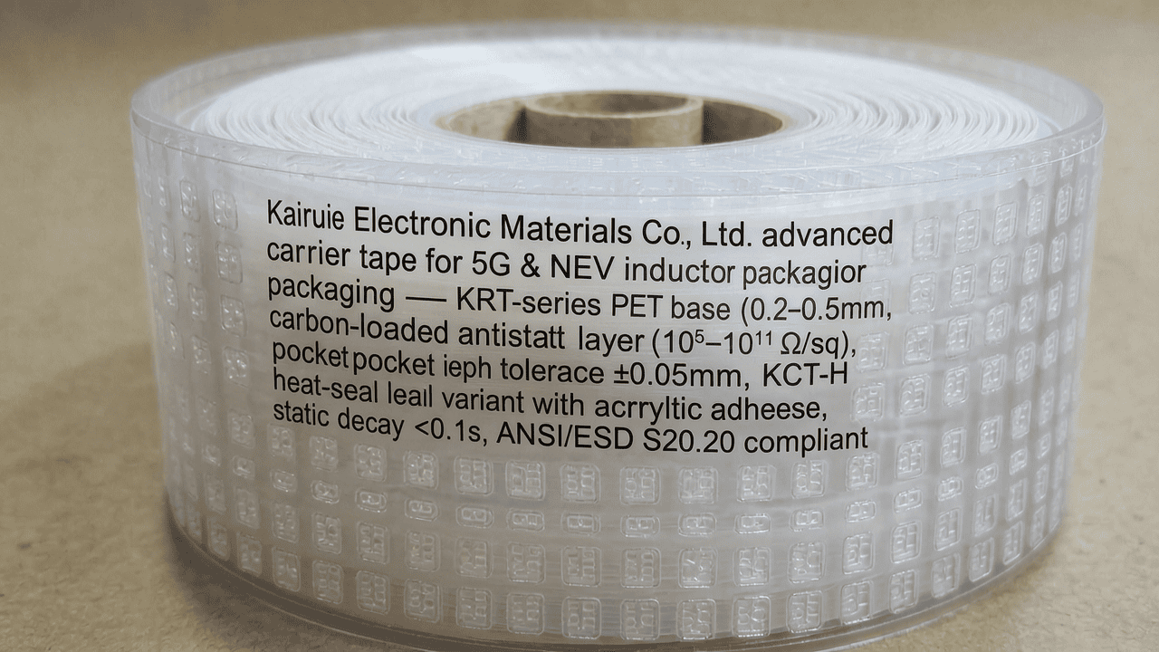
2.2 Cover Tape Variants
Kairuie offers two main cover tape families: KCT-H for heat-seal applications and KCT-P for pressure-sensitive adhesive (PSA). The heat-seal tape features a PET film with a heat-activated adhesive layer that bonds reliably to the carrier tape at controlled temperatures. The PSA type uses an acrylic adhesive system that provides consistent peel strength without thermal stress. Both variants incorporate an antistatic top coating with a static decay time of less than 0.1 seconds, meeting ANSI/ESD S20.20 standards. Specific models like KCT-H10 (for 8-12 mm carrier tape) and KCT-P15 (for wider tapes) allow customers to match sealing mode with production requirements.
2.3 ESD Performance Parameters
For 5G and NEV inductors, ESD protection is paramount. Kairuie’s materials are tested for surface resistivity (106-109 Ω for conductive, 109-1011 Ω for dissipative), volume resistivity, and triboelectric charging. The proprietary K-Stat treatment ensures consistent resistivity across the entire reel length, verified by inline monitoring during slitting and spooling.
3. Core Process Parameter Control
Achieving optimal sealing performance requires precise control of temperature, pressure, and dwell time. Kairuie’s materials are designed with wide process windows to accommodate different taping machines, including the dual-mode systems described in the Knowledge Base.
3.1 Heat-Seal Parameters
For KCT-H series heat-seal cover tapes, recommended sealing temperatures range from 130°C to 160°C, with a pressure of 0.3-0.5 MPa and dwell time of 0.5-1.0 seconds. Lower temperatures may result in weak seals and component fallout, while excessive temperatures can cause PET deformation or adhesive degradation. The sealing iron temperature uniformity should be within ±5°C. Kairuie’s tapes exhibit stable peel strength (30-120 g per the EIA-481 standard) across this range.
3.2 Self-Adhesive Parameters
Pressure-sensitive tapes (KCT-P) require no heat, simplifying integration but demanding controlled application pressure of 0.4-0.6 MPa. Peel strength can be adjusted via roller pressure and speed. The adhesive’s viscoelastic nature ensures re-sealability for rework, but excessive pressure may cause adhesive transfer to the carrier tape, leading to contamination in the pick-and-place nozzle.
3.3 Process Window Optimization
To maximize yield, Kairuie recommends conducting a design of experiments (DOE) for each new component. Start at the median temperature and pressure, then adjust based on seal integrity and peel force. For high-speed lines (up to 40,000 components per hour), the dwell time may be reduced to 0.3 seconds, requiring higher temperatures (up to 170°C) with thermal-resistant PET grades. The dual-mode taping equipment referenced in the Knowledge Base allows quick switching, making it essential to recalibrate parameters when changing between heat-seal and PSA modes.
4. Common Issues & Troubleshooting
Despite robust materials, production challenges can arise. The table below summarizes typical problems and solutions when using Kairuie tapes for inductor packaging.
| Symptom | Root Cause | Solution |
|---|---|---|
| Inconsistent peel strength along tape length | Temperature fluctuation in sealing iron; uneven pressure | Calibrate heater PID; verify parallel alignment of sealing jaw; clean iron surface |
| Component movement or tilting in pocket | Excessive pocket clearance; inadequate tape tension | Select tighter pocket tolerance (e.g., KRT series with +0.0/-0.05 mm); adjust reeling tension to 0.5-1.0 N |
| Cover tape lifting after reeling | Insufficient initial tack or heat activation; reel diameter too small causing stress | Increase pressure or temperature slightly; use larger hub (≥10 cm) for high-component-count reels; store reels flat |
| ESD damage to components during de-reeling | Surface resistivity outside specification; tribocharging from improper material combination | Verify conductivity with surface resistivity meter; ensure carrier and cover tapes both have ESD control; use Kairuie‘s matched conductive pair (KRT-C and KCT-C) |
| Contamination on gold-plated inductor terminals | Outgassing from adhesive at high temperature; silicone transfer | Switch to Kairuie’s low-outgassing adhesive (KCT-EL series); reduce sealing temperature; ensure adequate ventilation in sealing zone |
5. Quality Inspection Standards
Kairuie implements a comprehensive quality control system aligned with IPC/JEDEC standards, ensuring every reel meets the demands of 5G and NEV applications.
5.1 Incoming Quality Control (IQC)
Upon receipt of raw materials and finished reels, inspectors check: visual defects (bubbles, wrinkles, contamination) under 10x magnification; dimensional accuracy using calibrated calipers and profilometers (pocket length/width ±0.05 mm, depth ±0.03 mm); peel strength tested at 300 mm/min per EIA-481; surface resistivity using a concentric ring probe. Any reel with resistivity outside 106-1011 Ω/sq is rejected. For cover tape, the adhesive transfer test on Kapton film ensures no residue.
5.2 In-Process Quality Control (IPQC)
During slitting and spooling, operators sample every 200 meters or once per hour. Critical checks include peel strength (target 40-80 g continuous), pocket dimension trending, and ESD parameter stability. Control charts (X-bar R) are used to detect drift. For KCT-H tapes, the seal integrity is verified by a vacuum bubble test on a sample sealed at nominal parameters.
5.3 Reliability Testing
Kairuie subjects its products to aging tests (60°C/90% RH for 500 hours), thermal cycling (-40°C to +85°C, 100 cycles), and vibration testing (random vibration 10-500 Hz, 3 axes) simulating transportation. Peel strength degradation must be <20% after aging. ESD properties are re-verified post-test. These tests ensure that inductors remain securely packaged even in harsh automotive under-hood environments or during air freight.
6. Selection Guide
Choosing the right carrier and cover tape combination depends on the inductor type, production volume, and sealing mode. The table below provides a quick reference for common 5G and NEV inductor scenarios.
| Component Type | Recommended Carrier Tape | Pocket Depth (mm) | Cover Tape | Sealing Mode |
|---|---|---|---|---|
| Small chip inductors (0201, 0402) for 5G RF modules | KRT-0803-H | 0.3 | KCT-H08 | Heat Seal |
| Power inductors (6×6 mm, 8×8 mm) for NEV DC-DC converters | KRT-1206-C or KRT-1608-C (custom) | 0.6-1.0 | KCT-P12 (PSA) | Self-Adhesive (or Heat Seal with KCT-H12) |
| High-current inductors (10×10 mm) with exposed terminals | KRT-2412-C | 1.2 | KCT-C12 (conductive) | Heat Seal |
| Miniature inductors for implantable medical devices (quality-critical) | KRT-0804-MD (medical-grade, ISO 13485 traceable) | 0.4 | KCT-H08-MD (low-outgassing) | Heat Seal |
For medium-batch production with frequent changeovers, Kairuie’s dual-mode compatible materials (KCT-H and KCT-P) allow a single reel setup to switch between sealing methods, minimizing downtime. The carrier tape width can be customized from 8 mm to 88 mm, supporting a wide range of component sizes.
7. Conclusion
As 5G and new energy vehicle technologies advance, the demands on inductor packaging will only intensify. Kairuie Electronic Materials Co., Ltd. rises to these challenges with a portfolio of SMT carrier and cover tapes that deliver precision, ESD integrity, and process flexibility. Our materials, from KRT-series carrier tapes to KCT heat-seal and pressure-sensitive cover tapes, are engineered to ensure zero-defect packaging from the taping line to the pick-and-place machine. With rigorous quality control and reliability testing, we support our customers in achieving high yields and long-term product reliability. To learn more about our solutions or to discuss your specific application, please visit our website at www.kairuie.com. We invite industry peers to exchange ideas and collaborate on next-generation packaging innovations.


