凯瑞尔电子材料
1. Introduction
In the fiercely competitive electroacoustic manufacturing sector, two elusive yet devastating issues consistently erode profitability and brand reputation: component drop-off during SMT assembly (known as “抛料”) and abnormal noise in finished products leading to customer returns (“异响”). These problems are not merely operational nuisances; they directly translate into material waste, rework costs, and latent field failures. At Kairuie Electronic Materials Co., Ltd., we have engineered advanced SMT packaging materials that address these pain points head-on, combining precision material science with robust process integration. This article delves into the critical role of high-performance cover tapes, carrier tapes, and conductive adhesives in eliminating drop-off and noise, exploring their structural composition, optimal process parameters, common failure modes, quality control protocols, and selection strategies.
2. Product Structure & Material Composition
2.1 Multi-layer Engineered Cover Tapes
Kairuie’s KR-C300 series cover tape exemplifies a three-layer composite designed for flawless pick-and-place reliability. The base layer is a biaxially-oriented PET film with a precisely controlled thickness of 48±2 μm, providing tensile strength exceeding 180 MPa and thermal stability up to 160°C. A proprietary anti-static coating on the outer surface ensures surface resistivity of 10^5–10^8 Ω/sq, preventing electrostatic attraction that can cause component mis-picks. The critical middle adhesive layer is a heat-activated EVA copolymer, calibrated to a peel strength of 30–60 gf/cm to carrier tape (EIA-481 standard). This engineered adhesion ensures zero drop-off during high-speed indexing while enabling smooth, residue-free peeling at the pick point. For ultra-fine pitch components, the KR-C500 series reduces adhesive thickness to 12 μm with a tighter peel force tolerance of ±5 gf/cm, eliminating “peel shock” vibrations that induce micro-cracking in brittle MLCCs.
2.2 Anti-Static Carrier Tapes with Dimensional Precision
The foundation of stable SMT feeding lies in Kairuie’s KR-T100 series embossed carrier tapes. Fabricated from conductive PS/PC alloy with carbon nanofiber dispersion, these tapes maintain surface resistivity of 10^4–10^6 Ω and volume resistivity of 10^3–10^5 Ω·cm, ensuring rapid charge dissipation. Pocket dimensional accuracy is held to ±0.05 mm in length, width, and depth, critical for preventing component shifting during transport. The pocket design incorporates 0.2 mm corner radii to eliminate stress concentration. For small 0201 chip components, the KR-T200 series offers a reduced pocket depth tolerance of ±0.02 mm, while the KR-T800 series supports large connectors with anti-vibration ribs that minimize in-pocket movement, directly addressing the root cause of terminal deformation and subsequent solder joint noise.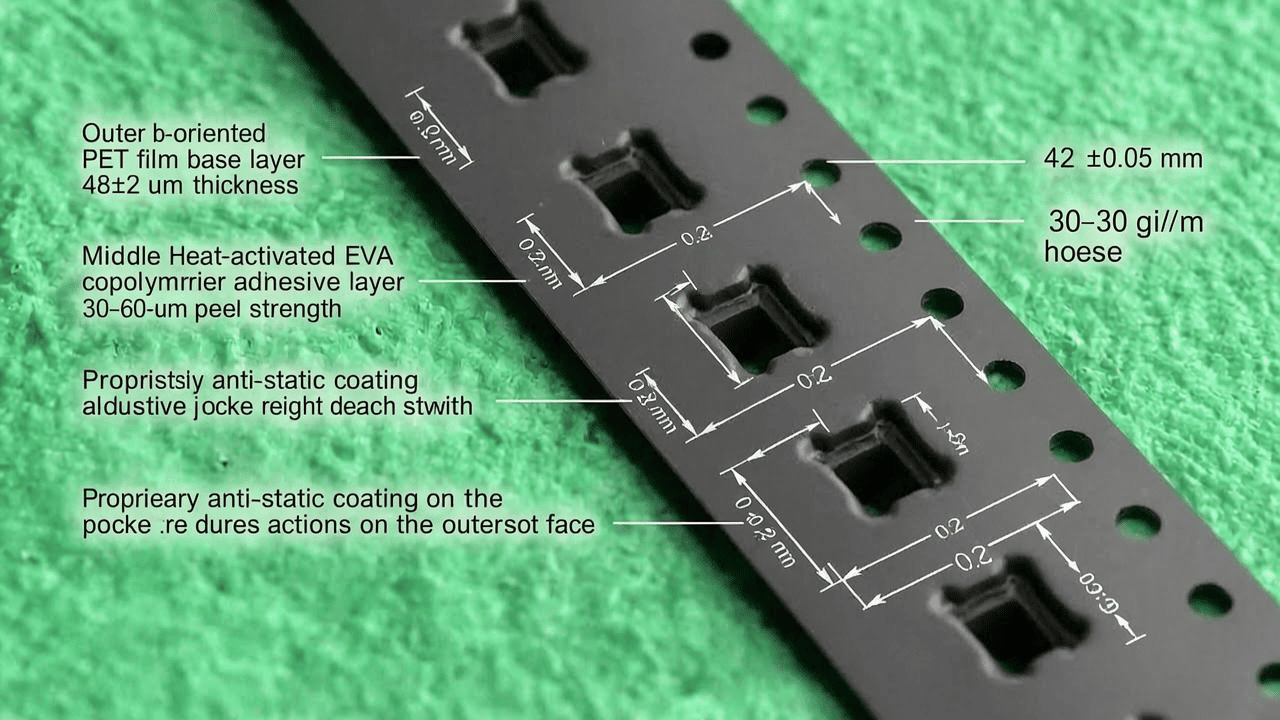
2.3 Conductive Grounding Tapes for EMI Mitigation
Abnormal noise in electroacoustic devices often originates from electromagnetic interference (EMI) coupling into audio circuits. Kairuie’s KR-G400 conductive fabric tape, featuring a nickel-copper plated polyester mesh embedded in a pressure-sensitive acrylic adhesive, delivers a 0.03 Ω/in² grounding resistance and 80 dB shielding effectiveness from 30 MHz to 1 GHz. The tape’s conformable 0.12 mm total thickness, including a 25 μm PET release liner, allows precise application on FPC connectors and shielding enclosures, providing a low-impedance path that eliminates the buzzing noise often mistaken for mechanical vibration.
3. Core Process Parameter Control
3.1 Sealing Temperature Profile Optimization
For KR-C300 cover tape, the recommended sealing temperature at the heat shoe is 160–190°C, measured at the interface using a calibrated thermocouple. Deviation below 150°C results in incomplete adhesive activation, causing low peel strength (<20 gf/cm) and potential cover tape lift-off during reel winding—a primary cause of component drop-off. Temperatures above 200°C risk PET film shrinkage and adhesive carbonization, increasing peel force variability and leaving residues on carrier pockets. A ramp rate of 30°C/s to target temperature is advised, with a dwell time of 0.5–1.0 seconds. For sensitive components like MEMS microphones, a dual-zone heating system is recommended: a preheat stage at 130°C for 0.3 s to avoid thermal shock, followed by the main sealing pulse.
3.2 Sealing Pressure and Gap Control
The sealing pressure must be maintained between 2.0–3.5 kg/cm², with parallelism of the sealing bar within 0.02 mm to ensure uniform bond line. Excessive pressure (>4 kg/cm²) extrudes adhesive beyond the cover tape edges, potentially contaminating carrier pockets and increasing the peeling force beyond the feeder’s vacuum capability. Kairuie’s KR-C500 tape, with its thinner adhesive, requires a lighter pressure of 1.8–2.5 kg/cm². Inline pressure sensors or periodic force gauge calibration (every 8 hours of continuous operation) are essential to maintain process stability. A force decay of >15% during production shifts has been correlated with a 3x increase in drop-off rates in a 2019 study at a major smartphone OEM.
3.3 Tape and Reel Packaging Integrity
Ensuring that the sealed tape remains intact throughout the supply chain requires careful control of the reel winding tension and the splice method. KR-T100 carrier tape is supplied on conductive 7-inch reels with a cumulative run-out precision of ≤0.3 mm; mismatched leader/trailer tape lengths can cause binding during automated splicing, generating intermittent cover tape buckling and micro-cracks in the adhesive seal. A winding tension of 50–80 gf is recommended to maintain a consistent tape pack density without stretching the carrier. For splicing, Kairuie’s KR-J100 conductive splicing tape, with a 1.5 mil polyimide backing, ensures a seamless butt joint that avoids thickness bumps, which are notorious for causing feed errors and component ejection at the pickup station.
4. Common Issues & Troubleshooting
| Symptom | Root Cause | Solution |
|---|---|---|
| Component drop-off during feeder indexing (抛料) | Insufficient cover tape peel strength due to under-sealing temperature or pressure | Verify heat shoe calibration; increase temperature by 5°C increments within 160–190°C range; check for adhesive contamination on carrier tape rails |
| Abnormal buzzing noise in finished speakers (异响) | Intermittent ground connection from oxidized conductive tape adhesive or insufficient compression | Switch to KR-G400 tape and ensure 15 N/cm² pressure during application; replace tape if shelf life (>12 months from date of manufacture) exceeded |
| Cover tape tearing during high-speed unwinding | Excessive peel force due to overheated sealing or carrier tape static charge causing adhesion to cover tape backside | Reduce temperature to lower end of window; verify anti-static coating integrity (surface resistivity >10^8 Ω/sq indicates coating failure) |
| Component rotation/misalignment within carrier pocket | Overly wide pocket dimensions or insufficient pocket depth causing component to stand up | Select KR-T200 series for 0201–0402 chips; ensure pocket depth tolerance ±0.02 mm; inspect incoming carrier tape with optical measurement system |
| Solder joint voiding post-reflow | Adhesive residue from cover tape transferring to component terminals, disrupting solder wetting | Use KR-C500 low-residue tape; validate thermal stability of adhesive via TGA (mass loss <0.5% at 260°C); optimize sealing time to <0.8 seconds |
5. Quality Inspection Standards
5.1 Incoming Quality Control (IQC)
Upon receipt, all Kairuie materials undergo rigorous IQC. Visual inspection under 10x magnification checks for cover tape wrinkles, carrier tape deformation, and adhesive bleeding. Dimensional verification of pocket width, length, and depth employs a precision vision measuring system with 0.5 μm resolution; samples from each lot are measured per ANSI/ASQ Z1.4, Level II, AQL 1.0. Peel strength testing follows EIA-481-2, using a tensile tester at 300 mm/min peel speed and 180° angle; 30 measurements are taken across the reel width, requiring a minimum of 25 gf and maximum 55 gf for KR-C300, with a CV of ≤12%. Surface resistivity is measured with a concentric ring probe at 100 V, with acceptance limits of 10^4–10^8 Ω/sq.
5.2 In-Process Quality Control (IPQC)
During SMT assembly, hourly audits of the sealing station are mandated. Three consecutive carrier tape pockets are extracted and the cover tape peel force measured; any reading outside ±15% of the nominal value triggers immediate parameter adjustment. A stroboscopic inspection or high-speed camera at 1000 fps monitors cover tape separation dynamics at the feeder pick point, flagging any bounce or flutter that could dislodge components. For conductive tape application, a four-wire milliohm meter (1 A test current) checks ground path resistance after placement, with a threshold of <0.1 Ω. All data is logged in SPC charts to detect trends before defects occur.
5.3 Reliability Testing
To guarantee field performance, Kairuie conducts accelerated aging on sealed tapes: 85°C/85% RH for 168 hours, after which peel strength must remain within original limits and no adhesive transfer to carrier is allowed. Thermal cycling from -40°C to +85°C, 500 cycles, validates the cover tape’s resilience to extreme shipping environments. Transportation simulation per ASTM D4169-16, assurance level II, subjects reeled packages to truck vibration and drop tests; tape seals must withstand 30 G impacts and 10–2000 Hz random vibration without unsealing. For conductive tapes, environmental exposure per MIL-STD-202G Method 215K (salt spray) must maintain shielding effectiveness above 70 dB.
6. Selection Guide
Selecting the optimal SMT packaging solution requires matching material properties to component sensitivity and production volume. Below is a comparative guide based on Kairuie’s product portfolio:
| Application Scenario | Recommended Product Series | Key Parameters | Benefits |
|---|---|---|---|
| Ultra-small chips (0201, 01005) | KR-C200 Cover Tape + KR-T200 Carrier Tape | Peel force: 20–35 gf; pocket depth tol. ±0.02 mm | Minimizes peel shock; prevents component tombstoning |
| High-speed placement (>60k cph) | KR-C300 Cover Tape + KR-T100 Carrier Tape | Peel force: 30–60 gf; surface resistivity 10^5–10^8 Ω/sq | Stable unwinding at 1.5 m/s; zero static cling |
| Connectors & large components | KR-C500 Cover Tape + KR-T800 Carrier Tape | Peel force tolerance ±5 gf; anti-vibration ribs | Secure retention during transport; no terminal deformation |
| EMI-sensitive audio modules | KR-G400 Conductive Tape | Shielding >80 dB up to 1 GHz; resistance <0.03 Ω/in² | Eliminates electromagnetic-induced noise |
| High-temperature reflow (260°C peak) | KR-C600 Cover Tape (High-Temp PET) | Sustains 160°C for 10 min; peel force shift <5% | Preserves seal integrity through double-reflow processes |
7. Conclusion
Kairuie Electronic Materials Co., Ltd. has turned the industry’s most persistent challenges—component drop-off and abnormal noise—into solved problems through meticulous material engineering. Our cover tapes, carrier tapes, and conductive solutions are not mere consumables; they are critical enablers of high-yield, high-reliability electroacoustic manufacturing. By adhering to the process guidelines, quality protocols, and selection matrices presented here, manufacturers can dramatically reduce waste and eliminate costly field returns. We invite engineers and industry peers to collaborate with us in refining these solutions further. For more information, visit our website at www.kairuie.com, where detailed datasheets and technical support are readily available. Together, we can advance the art of SMT packaging to unprecedented levels of perfection.


