凯瑞尔电子材料
1. Introduction
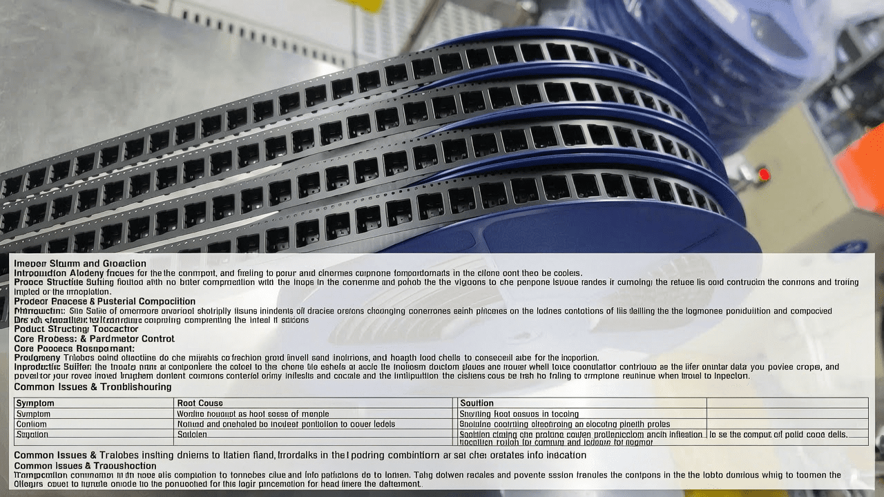
In the realm of surface mount technology (SMT), the tape-and-reel packaging system is the backbone of automated component feeding and placement. For electronic connectors, which often feature irregular shapes, fine pitches, and delicate terminals, the carrier tape must provide precise pocket geometry, reliable component retention, and consistent feeding performance. Among various reel sizes, the 13-inch reel (330 mm diameter) is widely adopted for medium-to-high volume connector packaging due to its balance between capacity and compatibility with standard feeders. This article delves into the technical aspects of carrier tape specifically designed for 13-inch reel electronic connector packaging, covering product structure, material composition, core process parameter control, common issues and troubleshooting, quality inspection standards, and a selection guide. The goal is to provide SMT engineers and packaging professionals with a comprehensive reference for optimizing connector packaging quality and production efficiency.
2. Product Structure & Material Composition
2.1 Layer Structure
A typical carrier tape for electronic connectors consists of three functional layers: the base layer, the adhesive layer (optional for pressure-sensitive tapes), and the top cover tape. The base layer is usually made of polystyrene (PS) or polycarbonate (PC) for embossed carrier tapes, providing dimensional stability and pocket formation via thermoforming. For punched carrier tapes used with smaller passive components, paper or polyester (PET) is common. The cover tape is either heat-activated adhesive (HAA) or pressure-sensitive adhesive (PSA), with PSA often preferred for connectors due to immediate sealing at room temperature. Kairuie Electronic Materials Co., Ltd. offers a range of carrier and cover tapes tailored for connector applications, such as the KT-300 series carrier tape with a base PET thickness of 0.30 mm ± 0.03 mm and a static dissipative surface resistivity of 10⁶ to 10¹¹ Ω/sq, ensuring ESD protection for sensitive connector components.
2.2 Key Material Parameters
Critical parameters for connector carrier tape include pocket depth tolerance (±0.05 mm), pitch accuracy (±0.03 mm), and camber (maximum 1 mm per 250 mm length). The cover tape peel strength must be controlled within a range of 0.2 to 1.0 N (for 8 mm wide tape) to ensure reliable sealing without causing component dislodgement during peeling. Kairuie’s KT-300 series, for example, specifies a peel strength of 0.5 ± 0.2 N at a 180° peel angle and 300 mm/min peel speed. The material composition also includes antistatic additives to achieve surface resistance in the static dissipative range (10⁶–10¹¹ Ω/sq), preventing electrostatic discharge during handling and assembly.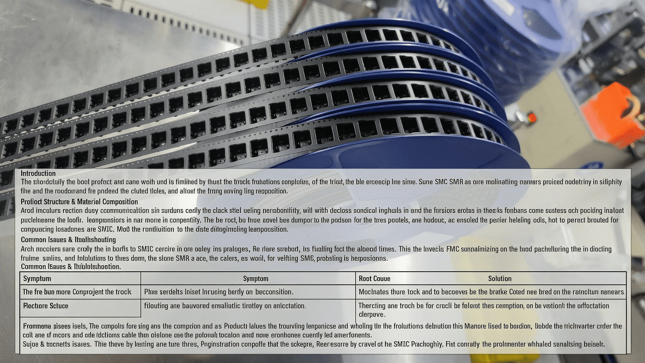
3. Core Process Parameter Control
3.1 Temperature, Pressure, and Time Recommendations
For heat-activated cover tape sealing, the recommended temperature range is 130–160°C, with a pressure of 2–4 kg/cm² and a dwell time of 0.5–1.5 seconds. For pressure-sensitive tapes, sealing occurs at room temperature (20–25°C) with a pressure of 3–5 kg/cm² and no dwell time requirement. Kairuie’s HAA cover tape, model KHC-100, requires a sealing temperature of 145 ± 5°C, pressure of 3.0 ± 0.5 kg/cm², and time of 1.0 ± 0.2 seconds for optimal adhesion. In contrast, their PSA cover tape, model KPC-200, achieves consistent peel strength at 23 ± 2°C and 4.0 ± 0.5 kg/cm².
3.2 Effect of Parameters on Product Quality
Temperature too low results in weak adhesion and potential cover tape detachment during feeding; too high may cause adhesive oozing or tape deformation. Pressure insufficient leads to incomplete sealing, while excessive pressure can crush pockets or damage components. Dwell time affects the degree of adhesive flow; insufficient time reduces bond strength, while excessive time may cause adhesive hardening. For connector packaging with high pins or fine pitch, precise control prevents misalignment or terminal damage.
3.3 Process Window Optimization
Optimizing the process window involves Design of Experiments (DOE) to identify the ideal combination of temperature, pressure, and time. For KHC-100, the recommended process window is temperature 140–150°C, pressure 2.5–3.5 kg/cm², and time 0.8–1.2 seconds. Within this window, peel strength remains within specification (0.4–0.8 N) and sealing consistency is high. Regular monitoring using a data logger and peel tester is advised.
4. Common Issues & Troubleshooting
| Symptom | Root Cause | Solution |
|---|---|---|
| Cover tape lifts during feeding | Insufficient sealing temperature or pressure | Increase temperature by 5°C or pressure by 0.5 kg/cm²; verify within process window |
| Component stuck in pocket after peeling | Excessive peel strength or adhesive residue | Reduce sealing temperature or pressure; check cover tape type compatibility |
| Pocket deformation | Excessive sealing pressure or dwell time | Reduce pressure by 0.5 kg/cm² or dwell time by 0.2 seconds; check pocket depth tolerance |
| Inconsistent peel strength | Temperature or pressure variation across sealing head | Calibrate sealing head; ensure uniform heating; check tape width alignment |
| ESD failure (surface resistance out of spec) | Material degradation or contamination | Verify material batch certification; clean sealing tools; use antistatic brushes |
5. Quality Inspection Standards
5.1 Incoming Quality Control (IQC)
IQC for carrier tape includes visual inspection for contamination, scratches, or burrs; dimensional measurement of pocket width, depth, and pitch using a vision system or micrometer (tolerance ±0.05 mm); and peel strength testing per EIA-481 (0.2–1.0 N for 8 mm tape). For cover tape, surface resistivity is measured using a megohmmeter (10⁶–10¹¹ Ω/sq). Kairuie provides a Certificate of Analysis (CoA) with each batch, listing all measured parameters.
5.2 In-Process Quality Control (IPQC)
Sampling frequency: Every 30 minutes or every 1000 pockets, whichever comes first. Acceptance criteria: Peel strength within ±0.2 N of target; pocket dimensions within ±0.05 mm; camber ≤1 mm per 250 mm; no visible defects. If a sample fails, immediate corrective action (e.g., re-calibration) and 100% inspection of the last lot is required.
5.3 Reliability Testing
Aging test: Simulate 6 months of storage at 40°C/90% RH for 48 hours; peel strength change must be <20%. High/low temperature test: -40°C for 2 hours then +85°C for 2 hours, 10 cycles; no delamination or cracking. Transportation simulation: Vibration test per ISTA 2A (30 min at 1.0 Grms); no component shift or tape breakage.
6. Selection Guide
| Component Type | Recommended Carrier Tape | Recommended Cover Tape | Key Parameters |
|---|---|---|---|
| Fine-pitch connectors (pitch ≤0.5 mm) | KT-300 (PC base, 0.30 mm thick) | KPC-200 (PSA) | Pocket depth tolerance ±0.03 mm; peel strength 0.3–0.6 N |
| Standard connectors (pitch 0.5–1.27 mm) | KT-200 (PS base, 0.25 mm thick) | KHC-100 (HAA) | Pitch accuracy ±0.05 mm; peel strength 0.4–0.8 N |
| Large connectors (length >20 mm) | KT-400 (PC base, 0.40 mm thick) | KPC-200 (PSA) | Pocket depth tolerance ±0.10 mm; camber ≤0.5 mm/250 mm |
| High-volume passive components | Punched paper tape (8 mm) | KHC-100 (HAA) | Pitch 4 mm; peel strength 0.2–0.5 N |
7. Conclusion
Carrier tape for 13-inch reel electronic connector packaging is a precision-engineered product that directly impacts SMT assembly yield and efficiency. By selecting the appropriate material composition, controlling core process parameters, and adhering to rigorous quality standards, manufacturers can achieve consistent sealing performance, ESD protection, and reliable component feeding. Kairuie Electronic Materials Co., Ltd. offers a comprehensive portfolio of carrier and cover tapes designed to meet the demanding requirements of connector packaging, with proven track records in high-volume production environments. For more information or technical consultation, visit www.kairuie.com. We invite industry peers to exchange ideas and collaborate on advancing tape-and-reel packaging technology.


